
Upgrade your RC Transmitter with a DIY Tilt Motion Control Module

The described RC transmitter circuit integrates a potentiometer for each axis, which serves as a voltage divider. The output voltage varies from 0.5V to 2.5V, where 2.5V represents the neutral position. This voltage is crucial as it is fed into the analog input of the transmitter, which converts it into a 1.2ms pulse for RF transmission. The module's role includes amplifying and shifting the output of the accelerometer, which typically ranges around 1.65V ± 0.4V, to align with the potentiometer's output range.
An operational amplifier, configured as an inverting amplifier, is the main component for this voltage adjustment. The reference voltage (Vref) is manually set to ensure proper output tuning. The theoretical calculations for the op-amp's behavior are grounded in feedback principles, where the voltages at the inverting and non-inverting terminals stabilize to equal the reference voltage. Practically, this is fine-tuned using a trimmer resistor (R3) while ensuring the accelerometer is in a horizontal position, yielding an output of 1.65V.
The construction of the circuit can be carried out on a proto-board, with all necessary components and their respective part numbers clearly indicated in the schematic provided. The connection details to the transmitter are further elucidated in the accompanying images, ensuring clarity in the assembly process.
For the accelerometer, options include using an Acc_Gyro module or creating a custom break-out board tailored to specific requirements. The physical installation of the module is critical; it should be mounted beneath the antenna using double-sided foam tape to mitigate the effects of vibration, thereby enhancing the accuracy of readings.
Powering the module is achieved through the potentiometer contacts, which supply +5V. A simple LED test can confirm that the power contacts can provide a minimum of 20mV, while the module itself operates with a low current draw of less than 5mA. The project may utilize a custom-built accelerometer break-out board, although numerous pre-assembled alternatives are available on the market. An analog accelerometer is essential for the successful implementation of this project, ensuring accurate data transmission and response.The RC transmitter uses a potentiometer for each axis, it acts as a voltage divider sending a voltage of 0. 5V (the middle position corresponds to 2. 5V) to the analog input that is converted into a pule of 1. 2ms that is sent over RF. This module converts (amplifies and shifts) the accelerometer analog output, usually 1. 65 +/- 0. 4V to the same rang e of the potentiometer and sends it to the transmitter instead. An op-amp in an inverting amplifier configuration is used. Vref is set manually by tuning the output to be 2. 5V (or the PWM pulse to be 1. 5 ms). However it is possible to calculate the theoretical value as follows: Note that according to the rules of a feedback op-amp the voltage on it`s inverting/non-inverting terminals tends to equalize so V(+) = V(-) and in our case = Vref. Well, this is the theoretical value, in practice we adjust the trimmer R3 until the output is 2. 5 while the accelerometer is in laying in horizontal position (has an output of 1. 65V). To build use a small proto-board following schematic. Part numbers are mentioned on schematic. Hook-up with the transmitter is described in images below and on the schematic. For accelerometer use Acc_Gyro or similar module, or build your own accelerometer break-out board. The module is mounted in a free space under antenna using double-sided foam tape best way to mount an accelerometer to avoid vibration.
Note that we get +5V power for the module from the potentiometer contacts. You can test with a led that the power contacts can deliver at least 20mV, the module uses far less <5mA. Here is a close-up of the module, as you can see I did my own accelerometer break-out board, but you can buy a pre-assembled one, there are many choices. You will need an analog accelerometer for this project. 🔗 External reference
Related Circuits
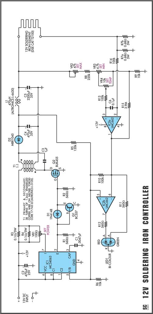
One reason commercial soldering stations are costly is that they typically use soldering irons equipped with built-in temperature sensors, like thermocouples. This circuit design eliminates the necessity for a specialized sensor by directly sensing the temperature of a soldering...
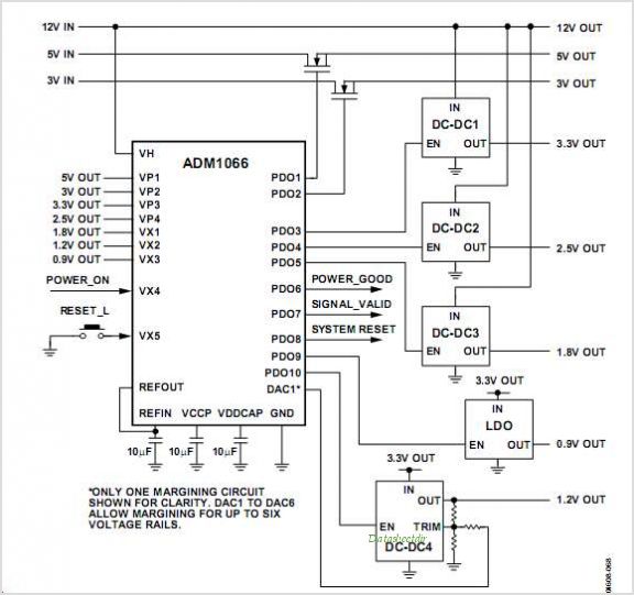
The ADRF6702 TxMod is an IQ modulator that includes an integrated phase-locked loop (PLL) and voltage-controlled oscillator (VCO). The PLL synthesizer employs a fractional-N PLL to produce a 2*FLO input for the I-Q modulator. The PLL reference input can...
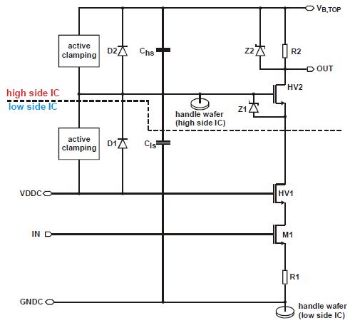
Integration of 1200V SOI gate driver ICs into a medium power IGBT module package. A novel approach for medium power applications. The integration of 1200V Silicon-On-Insulator (SOI) gate driver Integrated Circuits (ICs) into medium power Insulated Gate Bipolar Transistor (IGBT)...
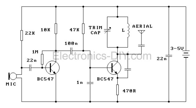
This FM transmitter is one of the simplest and most basic designs that can be built while still providing a useful transmitting range. Despite its small component count and 3V operating voltage, it is surprisingly powerful, capable of transmitting...
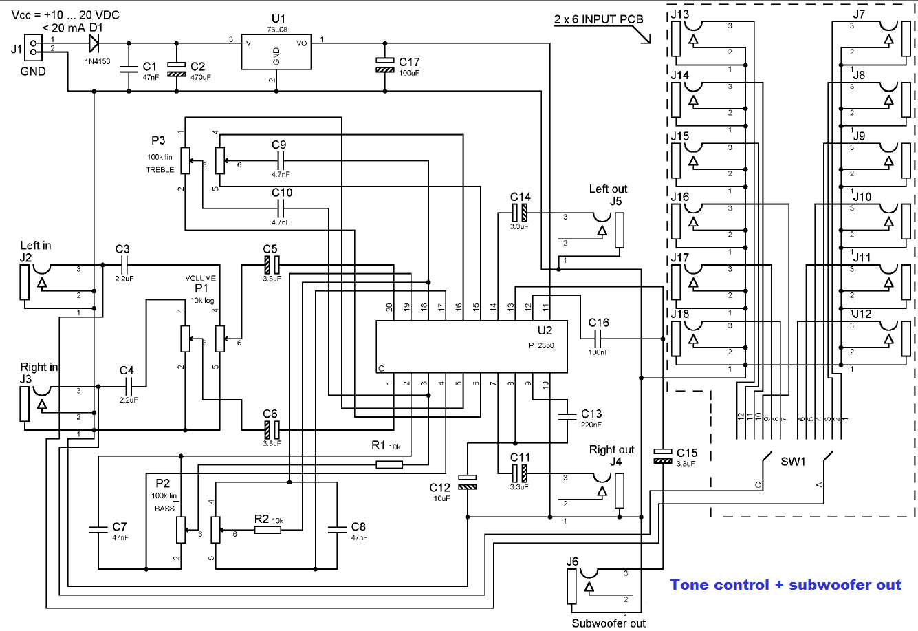
PT2350 is a tone control subwoofer crossover low pass filter chip utilizing CMOS technology. It features a tone control range of +10dB (50Hz, 4 kHz) and a subwoofer low pass filter of the second-order Sallen Key design. The roll-off...
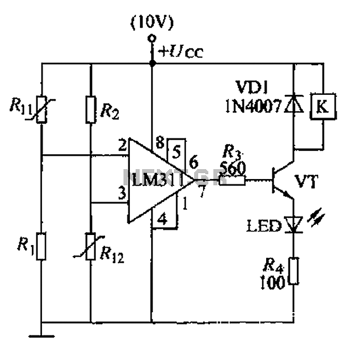
A boiler control circuit is designed to regulate the temperature of water in a hot water heating system. This circuit typically utilizes a comparator's comparison function to manage the heating equipment. The circuit includes a thermistor that forms a...