
USB car charger adapter circuit design

The USB car charger adapter circuit utilizing the LM317 voltage regulator is designed to convert a car's 12V DC power supply into a stable 5V output, suitable for charging USB-powered devices. The LM317 is a versatile adjustable voltage regulator that can provide a constant output voltage with a load current of up to 1.5A, making it ideal for charging applications.
In this circuit, the input voltage from the car battery (typically ranging from 12V to 14.4V) is fed into the LM317. The output voltage is set to 5V by using two external resistors connected to the adjustment pin of the LM317. The values of these resistors determine the output voltage according to the formula:
Vout = Vref (1 + R2/R1) + Iadj * R2
Where Vref is typically 1.25V. By selecting appropriate resistor values, the output can be accurately adjusted to 5V.
To ensure proper operation and stability, capacitors are placed at both the input and output of the LM317. A 0.1µF ceramic capacitor is recommended at the input to filter out any high-frequency noise, while a larger electrolytic capacitor (typically 10µF or more) is placed at the output to smooth the voltage and provide transient response during load changes.
Additionally, a heat sink may be necessary for the LM317 to dissipate heat generated during operation, especially when the input voltage is significantly higher than the output voltage. The circuit is typically enclosed in a compact housing with a USB output port for convenience, allowing users to easily connect and charge their devices.
Protection features such as a fuse or a resettable polyfuse can be included to prevent overcurrent conditions, ensuring the safety and reliability of the charger. The design can be further enhanced with LED indicators to show the charging status of the connected device. Overall, the LM317-based USB car charger circuit is an efficient and cost-effective solution for powering USB devices from a vehicle's electrical system.USB car charger adapter circuit design using LM317 regulator circuit 🔗 External reference
Related Circuits
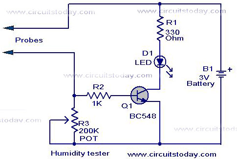
A simple humidity tester circuit using only an LED, a transistor, and a few resistors is explained with a clear circuit schematic. The humidity tester circuit is designed to provide a visual indication of humidity levels using basic electronic components....
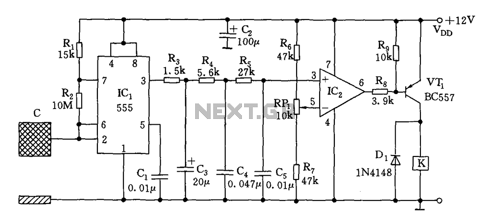
The switch circuit consists of a capacitive oscillator, an integration network, and a comparator circuit that controls a relay. When a body comes close to the induction plate, the inductive capacitance to ground increases, causing the 555 astable multivibrator...
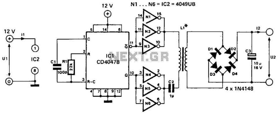
This low-power converter supplies approximately 100 mW of DC power to a load and is useful for isolating or deriving DC voltages. It operates at a frequency of around 200 kHz. The inductor is wound on a 22-mm diameter,...
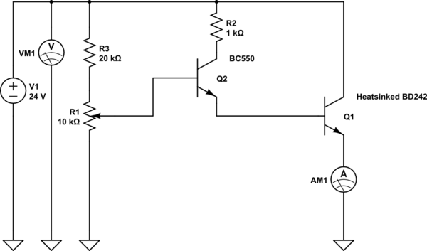
The device shows a voltage of 24V at no load on pins +4, 5 and -7, 8. This configuration is referred to as a passive power injector. When a current draw of 1A was attempted from the device, it...
The issue with sound cards is that they typically bandpass their input signals, making it challenging to record signals below 20Hz. Two potential solutions exist. The first involves modifying the sound card to eliminate the high-pass filter that blocks...
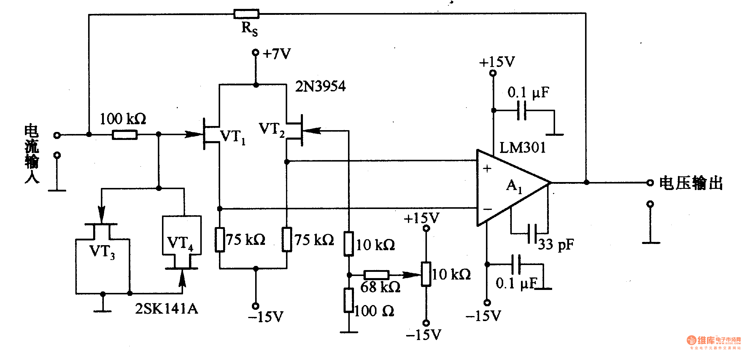
This is a low-input impedance conversion circuit with the reference resistor RS connected to the amplifier's feedback loop, resulting in an input impedance close to zero. The input current flows into the output end of the operational amplifier (Op-Amp)...