
Using 555 IC lighting lights one delay circuit

The 555 timer IC operates in monostable mode in this configuration, where it generates a single output pulse in response to a trigger signal. When the circuit is activated, the capacitor (C2) begins to charge through the resistor (Ri). The time it takes for the capacitor to charge to approximately 2/3 of the supply voltage determines the delay period before the output transitions from low to high. The delay time (T) can be calculated using the formula T = 1.1 × Ri × C2, where T is in seconds, Ri is in ohms, and C2 is in farads.
In this design, the absence of a light transformer means that the circuit can function independently of external lighting systems, making it versatile for various applications. The output from the 555 timer can be used to control other devices, such as relays or transistors, enabling the delayed activation of lights or other electronic components. The selection of Ri and C2 values allows for customization of the delay time to suit specific requirements, providing flexibility in timing applications.
This circuit is particularly useful in scenarios where a delay in lighting is desired, such as in automotive lighting systems, stage lighting, or safety applications where a gradual illumination is preferable. Proper attention should be given to the ratings of the components used, especially the capacitor and resistor, to ensure reliable operation over time.Using 555 lights lighting group delay IC circuit of the circuit shown in Figure 2-46. By the 555 IC and resistor-capacitor circuit composed of the delay. The circuit without light transformer T is still energized, energy. Delay time is determined by Ri, C2.
Related Circuits

When the preset is set to its maximum, the LED flashes at a rate of approximately once every half second. This rate can be increased by raising the capacitor value from 10µF to a higher value. For instance, if...
The MK484 AM receiver circuit is a simple design based on the MK484 AM receiver IC from Rapid Electronics Ltd. The MK484 is a monolithic integrated circuit that incorporates all necessary sections of an AM receiver, including an RF...
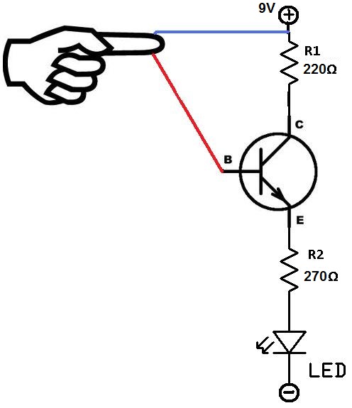
This project utilizes two wires, one red and one blue, which function as touch sensor wires. When a person touches both wires, the circuit closes, allowing current to flow and illuminate the LED. A 9-volt battery or an external...
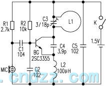
The loop antenna L1 is utilized for emission and also functions as the oscillation coil. The high-frequency current flowing through the antenna is synchronized in resonance with the oscillation frequency, ensuring optimal emission performance. Practical applications indicate that the...

When power is applied to the circuit, all Red LEDs will flash on and off simultaneously. The Yellow LEDs will also flash, but only every other Yellow LED will be illuminated at any given time. The Green LEDs will...
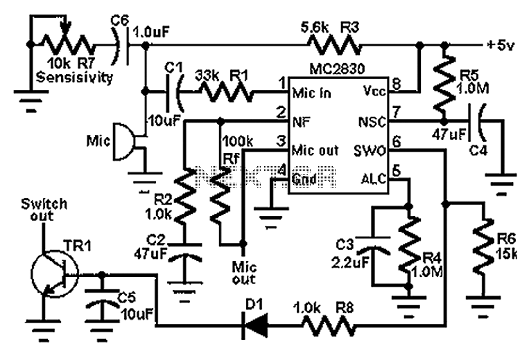
The circuit schematic utilizes the MC2830 voice circuit. Traditional voice circuits are unable to differentiate between speech and noise in the input signal. In noisy environments, such as those caused by switches, this limitation is significant. To address this...