
VALVE BASICS

The operation of a diode valve is fundamentally based on thermionic emission, where the heated cathode releases electrons into the vacuum. The electrons are attracted to the positively charged anode, which is essential for the diode's functionality. The construction of the valve ensures that the cathode is adequately heated, typically by a filament or heater, which is crucial for maintaining the thermionic emission process.
In practical applications, the diode valve serves as a rectifier, converting alternating current (AC) to direct current (DC). Its ability to conduct current in one direction while blocking it in the opposite direction is the key characteristic that enables this function. The efficiency and reliability of diode valves in high-frequency applications make them valuable components in radio frequency (RF) circuits, where they can serve as detectors or amplifiers.
When transitioning to a triode, the introduction of the control grid allows for modulation of the electron flow between the cathode and anode. This modulation is critical for amplifying signals, as varying the voltage on the control grid can influence the number of electrons that reach the anode, thereby controlling the output current. This principle forms the basis for many amplification applications in audio and radio frequency technologies.
The design considerations for these components include the choice of materials for the electrodes, the vacuum quality within the valve, and the thermal management of the filament. These factors directly impact the performance, longevity, and efficiency of the valve in various circuit applications.If you look into the bottom of a valve you will see the wires from each electrode and you can see the valve base pins to which they are connected. For this reason I will not give any valve data or pin-outs. These are widely available from other sources and most pin-outs can be worked out visually. I do not know why it is called a DIODE. With only two electrodes I reckon it should be called a BIODE. Basically, when an electrode (CATHODE) is placed in a vacuum, coated with Barium Oxide and heated to several hundred degrees, the electrons on its surface become more agitated and form a cloud around the cathode`s surface. From this cloud of electrons it is easy to attract electrons to a positively charged electrode (ANODE).
The anode only needs to be placed in the same vacuum as the cathode. Electrons will flow from the heated cathode to the relatively cool anode, but electrons will NOT flow from the anode to the cathode because there is no Barium Oxide coating on the anode and it is too cold. We have formed a DIODE valve. Here are the circuit symbols. The cathode is a bit of filament wire coated with Barium Oxide and a current is passed through it to make it get hot.
One of the two filament terminals is used as the cathode connection. This method of heating a valve cathode was most often used in battery portable equipment and HT rectifier valves. The filament voltage is normally 1. 4 volts for battery valves such as 1T4, 1L4, 1S4, DF91, DL91 etc. Directly heated HT rectifier valves commonly used 5 volts to heat them. Early valves used only 2. 5 volts for the filament. A huge disadvantage of a directly heated diode is that current flowing from cathode to anode is added to the filament current.
If this current becomes too large then the filament can become too hot and burn out, just like an overloaded torch-bulb. The non-coated filament wire is inserted into a Barium Oxide coated metal tube and insulated from it.
The filament is only used to heat the cathode tube and so it is normally called the HEATER. Here you can see a typical diode valve construction. (A) shows a typical filament wire with a wire support hook. Some valves use the wire support hook to make a direct electrical connection to the filament wire. This connection is used as a centre-tap for the cathode connection. Centre-tapped filaments are usually 2. 8 volts; 1. 4 volts between the centre-tap and each filament connection. (B) shows a typical indirectly heated cathode. (C) shows the anode assembled around the cathode. The anode may be circular or a variety of weird shapes. The diode valve is in many ways far superior to semiconductor diode because a semiconductor diode requires a certain voltage across its terminals before it begins to conduct. The vacuum tube diode does not suffer from this effect, making it an ideal and sensitive RF/IF detector.
Semiconductors will blow in microseconds whereas valves may last several seconds before something happens. In this way valves are more forgiving than transistors. To make an amplifying device (and to prevent the catastrophic scenario above) we need to regulate the current flowing from the cathode to the anode of a valve.
If we insert a wire mesh or GRID between the anode and the cathode we can control the electron flow and so we have created a TRIODE: This grid is called the CONTROL GRID. With a few hundred volts positive on the ANODE and the negative on the cathode, electrons from the electron cloud around the heated cathode w
🔗 External reference
Related Circuits
Create a repository of circuits and service data for vintage valve and transistor radios. While many resources are available online, they often come at a cost. The intention is to share circuits and manuals with others rather than profit...
The amplifier feeding the final amplification stage operates with unstabilized voltage. The output stage, utilizing push-pull operation, exhibits significant rejection of the supply voltage. However, the earlier stages do not provide the same level of rejection, resulting in unwanted...
Originally posted by ide2003, the message suggests that if one wishes to avoid using an operational amplifier (op-amp) entirely, it is highly recommended to consider ECDesign. The mention of avoiding op-amps in circuit design indicates a preference for alternative methods...
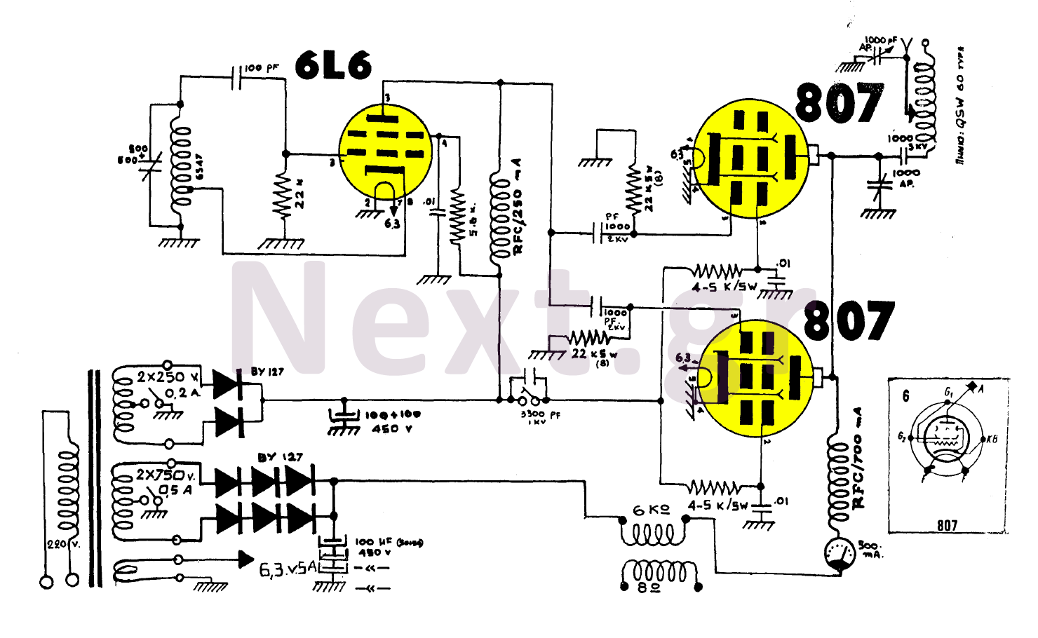
The construction utilizing two 807 tubes is robust and well-known for its performance. This design features high upward voltage and independent coupling on the output tubes, resulting in an increase in output power by several watts. While the output...
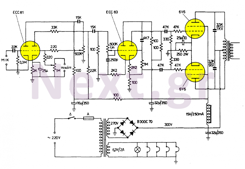
These two amplifiers are of high quality, simple, and economical to manufacture. They feature two inputs: one for a 4mV (500KΩ) sensitivity microphone and another for any 200mV (1MΩ) sound source, with the first input designated for speech and...
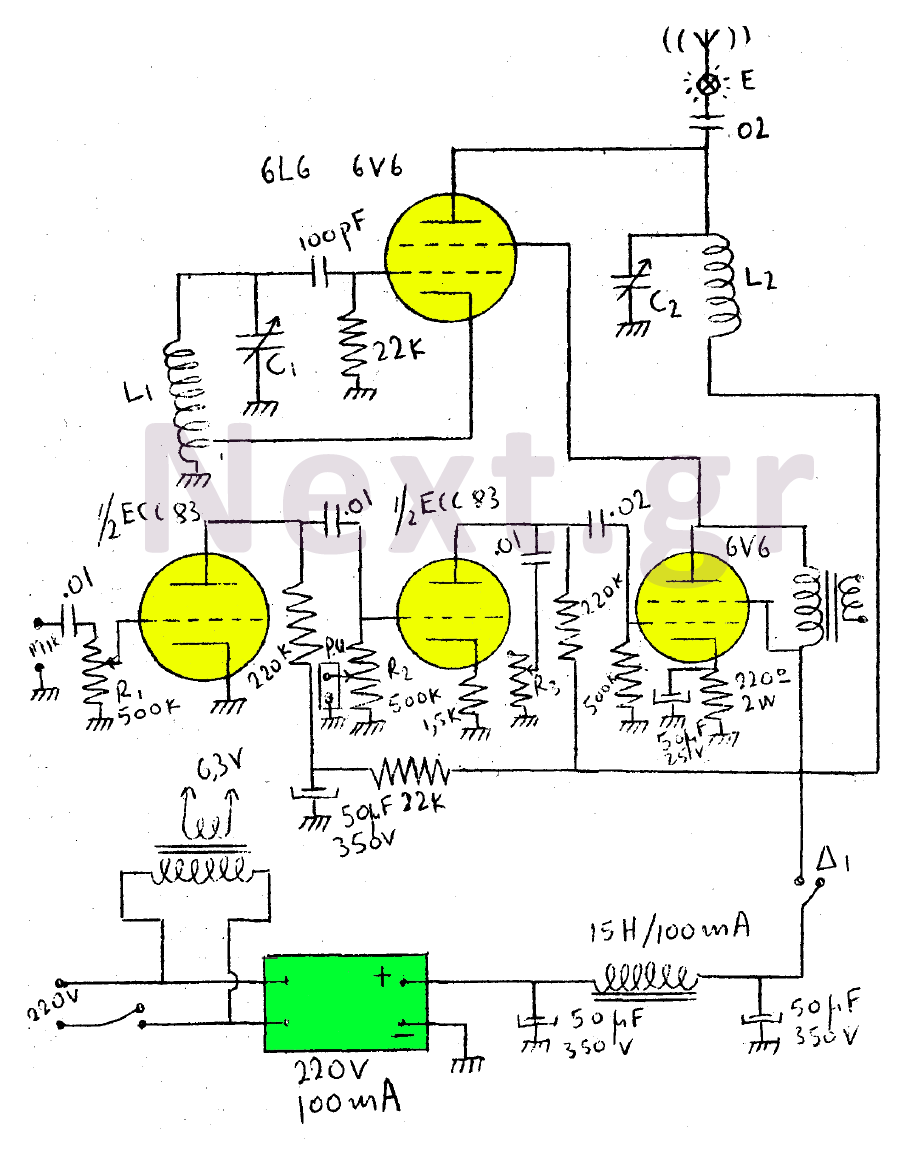
This circuit features a wearer assembly that includes a single lamp, either a 6V6 or 6L6, functioning as both an oscillator and an output amplifier. Coil L1 serves as the medium wave oscillation coil, while coil L2 is composed...