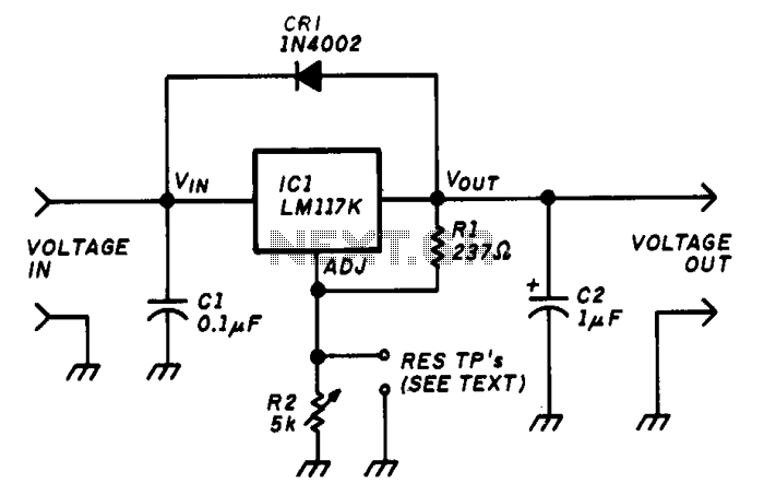
Variable-voltage-regulator

The variable voltage regulator allows for the adjustment of the output voltage of a fixed DC power supply between 1.2V and 37V DC, with the capability to supply output currents exceeding 1.5A. The circuit utilizes an LM117K three-terminal adjustable output positive voltage regulator housed in a TO-3 package. It includes thermal overload protection and short-circuit current limiting that is temperature compensated. Additionally, capacitor C1 mitigates sensitivity to input line impedance, while capacitor C2 minimizes excessive ringing. Diode CR1 prevents capacitor C2 from discharging through the integrated circuit during an output short.
The circuit design of the variable voltage regulator is centered around the LM117K voltage regulator, which is a popular choice for applications requiring adjustable voltage outputs. The LM117K features three terminals: input, output, and adjustment. The input terminal accepts the unregulated DC voltage, and the output terminal provides the adjustable regulated voltage. The adjustment terminal is connected to a voltage divider network, which sets the desired output voltage based on the feedback mechanism inherent within the LM117K.
Thermal overload protection is a critical feature of this design, ensuring that the regulator does not overheat during operation. This is achieved through internal circuitry that monitors the temperature of the device. If the temperature exceeds a certain threshold, the regulator reduces the output current to prevent damage. Similarly, the short-circuit current limiting feature protects the circuit from output shorts by limiting the maximum current flow, thereby safeguarding both the regulator and connected components.
Capacitor C1, typically a low-value electrolytic capacitor, is placed at the input to the LM117K to stabilize the input voltage against fluctuations caused by load changes or variations in the supply line impedance. This helps maintain a consistent output voltage even under varying load conditions. Capacitor C2, connected to the output, serves to dampen any high-frequency oscillations or ringing that may occur due to abrupt changes in load or input voltage. This is particularly important in maintaining the stability of the output voltage.
Diode CR1 is strategically placed to protect against reverse discharge of capacitor C2. In the event of an output short, without CR1, there is a risk that C2 could discharge through the LM117K, potentially damaging the regulator or affecting its operation. By allowing current to flow only in one direction, CR1 ensures that the integrity of the voltage regulator is maintained during fault conditions.
Overall, this variable voltage regulator circuit is designed to provide a reliable and adjustable output voltage with built-in protections, making it suitable for a wide range of electronic applications where precise voltage control is necessary.The variable voltage regulator lets you adjust the output voltage of a fixed de power supply between 1.2 and 37 V de, and will supply the output current in excess of 1.5 A. The circuit incorporates an LM117K three-terminal adjustable output positive voltage regulator in a T0-3 can.
Thermal overload protection and short-circuit current-limiting constant with temperature are included in the package. Capacitor C1 reduces sensitivity to input line impedance, and C2 reduces excessive ringing. Diode CR1 prevents C2 from discharging through the IC during an output short.