
Varying bulb luminosity using ATMEGA16
The circuit described incorporates several key components and functionalities that work together to achieve the desired control over light bulbs or motors. The TRIAC serves as the primary switching device, allowing for effective control of AC loads. The use of PWM for dimming or speed control is a well-established technique, and the choice of a microcontroller allows for advanced features such as zero-cross detection and timed operations.
The microcontroller's timer operates in CTC mode, which is efficient for generating precise timing intervals. The zero-crossing detection is crucial for synchronizing the TRIAC firing with the AC waveform, minimizing electrical noise and ensuring smooth operation. The opto-coupler provides isolation between the high-voltage AC side and the low-voltage control side, enhancing safety.
In terms of future developments, the system's ability to integrate USART or ADC for dynamic control opens up possibilities for user interfaces or sensor feedback, allowing for more responsive and intelligent lighting or motor control systems. The design considerations for inductive loads highlight the importance of protective measures in electronic circuits, ensuring reliability and longevity of components.
Overall, this schematic represents a versatile solution for controlling various loads in a smart home environment, with a focus on safety, efficiency, and expandability.We know that on the market there are plenty of devices that replace normal wall switches and let you adjust the luminosity of a bulb. But if you want to make an "intelligent" home or a more complicated device to adjust the power of a light bulb whatpossibilitiesdo you have 1.
If you are using DC, than it`s simple: just use a switching element ( a BJT or a MOSFET ). You just apply PWM (Pulse Width Modulation) and vary the duty cycle from 0% to 99% and you can adjust the luminosity of a lightbulb or LED or you can set the speed of a motor. If I would use a BJT to implement my application, I would have to consider that in the reverse active region thebehavior isdifferent from theforwardactive region.
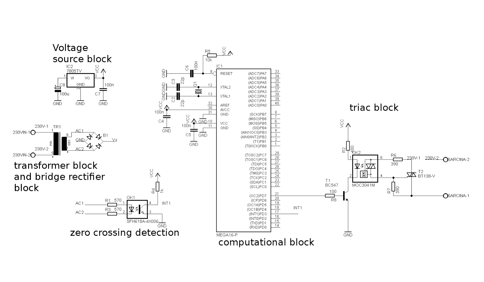
Because the application will be used at 50Hz(lowfrequency) to "drive" a light bulb (small load), and the maximum necessary current that will pass through it will be under 4 - 5 Amps, I have chosen to use a TRIAC. The same application can be easily modified(add some diodes) and can be used to drive high power loads(motors, heating elements, etc) using Thyristors.
1. The galvanic separation is used for safety. The transformer takes the 230V AC from the mains and gives on the output a voltage between 8 to 24V(which is safe tot touch). 2. Use the voltage from the secondary winding of the transformer to power up the uC, and also to detect de 0 crossings of the mains.
To power up the uC we need DC, so we take the AC from the transformer and afterrectifying(which include a bridge rectifier and a capacitor for filtering) block we obtain DC voltage 3. The uC uses 5V. We take the DC obtained at 2, use it as an input for the 7805 integrated circuit. At the output of the 7805 we will obtain 5Vstabilized. We will use this voltage to power up the uC. 4. Zero crossing detector - it`s just an opto-coupler. Internally, a diode lights up and turns on or off aphoto-transistorwhich pulls the output to GND. When the transistor is turned off, the output is pulled to VCC by the pull-up resistor. 5. When the output of the uC is HIGH, transistor Q0 is in saturation and the diode inside the opto-triac islighten and the BT136 TRIAC is fired (it conducts current from A1 to A2).
TIMER - internal structure of the microcontroller that counts. In our case the timer works in CTC "Clear Timer on Compare" mode. When TCNT(timer register that is incremented with every tick) is equal to OCR an interrupt is generated. When the sinus signal reaches almost 0V, in the detection block a rising or falling edge will be generated.
This edge, aplied to PD3(INT1) pin generate an interrupt. When the interrupt appears, the function ISR ( INT1_vect ) is called. It waits for 1ms(for the voltage to go down to 0 ) and then enables Timer 1 to start counting. the time for the delay until the trigger signal for the opto-triac will be given. When Timer 1 generates an interrupt(it has finished counting), PD3 pin is set to TRUE(5V) and the trigger signal is sent to the opto-triac which fires the triac that powers on the load (light bulb). Timer 1 is turned off and timer 0 starts counting. The program will be enhanced in the future to receive the data from USART or ADC and to be set dynamically using an algorithm.
Right now, everything is static. This is just a Proof Of Concept. If you want to drive a motor instead of a light bulb, no problem, but you have to use a snubber circuit to protect the TRIAC from damaging because of the inductive load or from auto-triggering. Also, it`s good practice to make the length of the signal until the sinus reaches 0, but it is a little tricky(it is not included in the code).
You have to adjust timer 1 for that. The same stuff can be done with ARDUINO, which uses Atmel microcontrollers and the code can be written in the same stile or using ARDUINO IDE ( I prefer using the presented style, and defenetly not Arduino IDE). 🔗 External reference
Related Circuits

The TPA2011D1 is a 3.2-W high-efficiency, filter-free Class-D audio power amplifier housed in a 1.21 mm x 1.16 mm wafer chip scale package (WCSP) that requires only three external components. This amplifier features 95% efficiency, an 86-dB power supply...
The LH0024 is a small signal integrated circuit (IC) designed for general-purpose switching and amplification due to its low voltage characteristics. Additionally, it utilizes three 1N4148 silicon small signal diodes, which are planar epitaxial devices used for fast switching...
This circuit also prevents the shutdown circuit of the IR2161 from operating in the normal way; therefore, an external SCR-based protection circuit needs to be added. The IR2161 is a high-voltage, high-speed driver designed for driving IGBTs and MOSFETs in...

This circuit utilizes three transistors (2SC945, 2C1815, or 2SC828) as the primary components, functioning as a typical low-noise transistor amplifier. It offers a gain of approximately 200 to 300 times and has a frequency response ranging from 50Hz to...
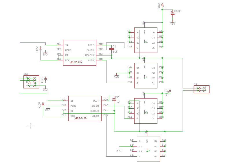
An H-bridge circuit was constructed using the TPS2836 and CSD16404 components. The schematic is provided below. However, the circuit is not functioning correctly, leading to several inquiries regarding potential design flaws. The power supply voltage (VDD-GND) is set to...
This circuit detects the dial tone from a telephone line and decodes the keypad pressed on the remote telephone. The dial tone heard when picking up the phone is referred to as Dual Tone Multi-Frequency (DTMF). This name originates...
Warning: include(partials/cookie-banner.php): Failed to open stream: Permission denied in /var/www/html/nextgr/view-circuit.php on line 713
Warning: include(): Failed opening 'partials/cookie-banner.php' for inclusion (include_path='.:/usr/share/php') in /var/www/html/nextgr/view-circuit.php on line 713