
Vco Circuit Circuit

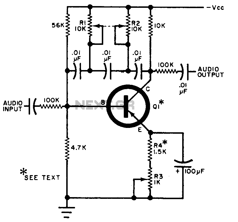
The described voltage-controlled oscillator (VCO) circuit employs the TL082 operational amplifier, which is known for its low noise and high-speed performance. The circuit configuration typically includes feedback components that create a positive feedback loop, essential for sustaining oscillations. The output frequency is influenced by the values of resistors and capacitors used in the feedback network, which dictate the timing characteristics of the circuit.
In this configuration, the TL082 op-amp operates in an inverting or non-inverting mode, depending on the design specifics. The frequency of the oscillation can be modulated by adjusting the bias supply voltage, which alters the gain and frequency response of the op-amp. This provides a versatile means of generating sinusoidal waveforms at various frequencies, making the circuit suitable for applications such as signal generation, modulation, and testing.
The circuit may also include additional components such as diodes for waveform shaping or filtering capacitors to refine the output signal. The simplicity and low cost of the design make it an attractive choice for both educational purposes and practical applications in electronic projects. Careful selection of components and layout considerations are essential to ensure stable oscillation and minimize distortion in the output waveform. The output frequency of this simple low-cost active voltage-controlled oscillator circuit is based upon the inherent frequency dependent characteristics of our operational amplifier. The oscillator circuit shown uses a TL082 op amp. When power is applied, the circuit generates a sinusoidal wave. The frequency of oscillation can be changed by varying the bias supply.
Related Circuits
Have you ever witnessed the stairs to an upper story in your home transform into a waterfall? Or perhaps you have returned home to find your aquarium fish attempting to swim across the carpet? For your sake, it is...
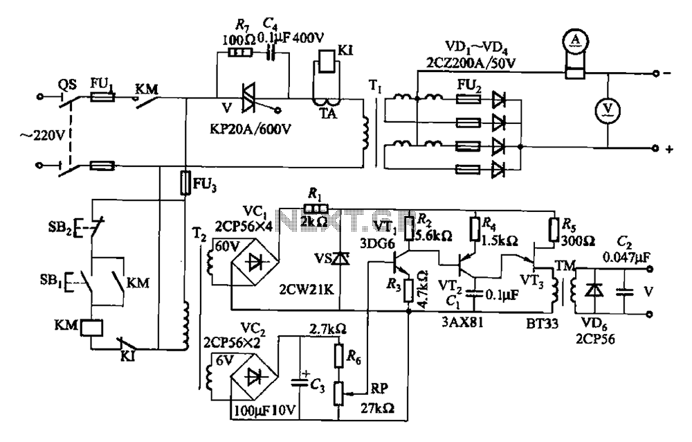
A 500A-6V single-phase power supply circuit designed for thyristor electroplating. This circuit can output a continuous DC current of 500A at 6V, which is adjustable for plating processes. It incorporates a single-junction transistor as part of the trigger circuit,...
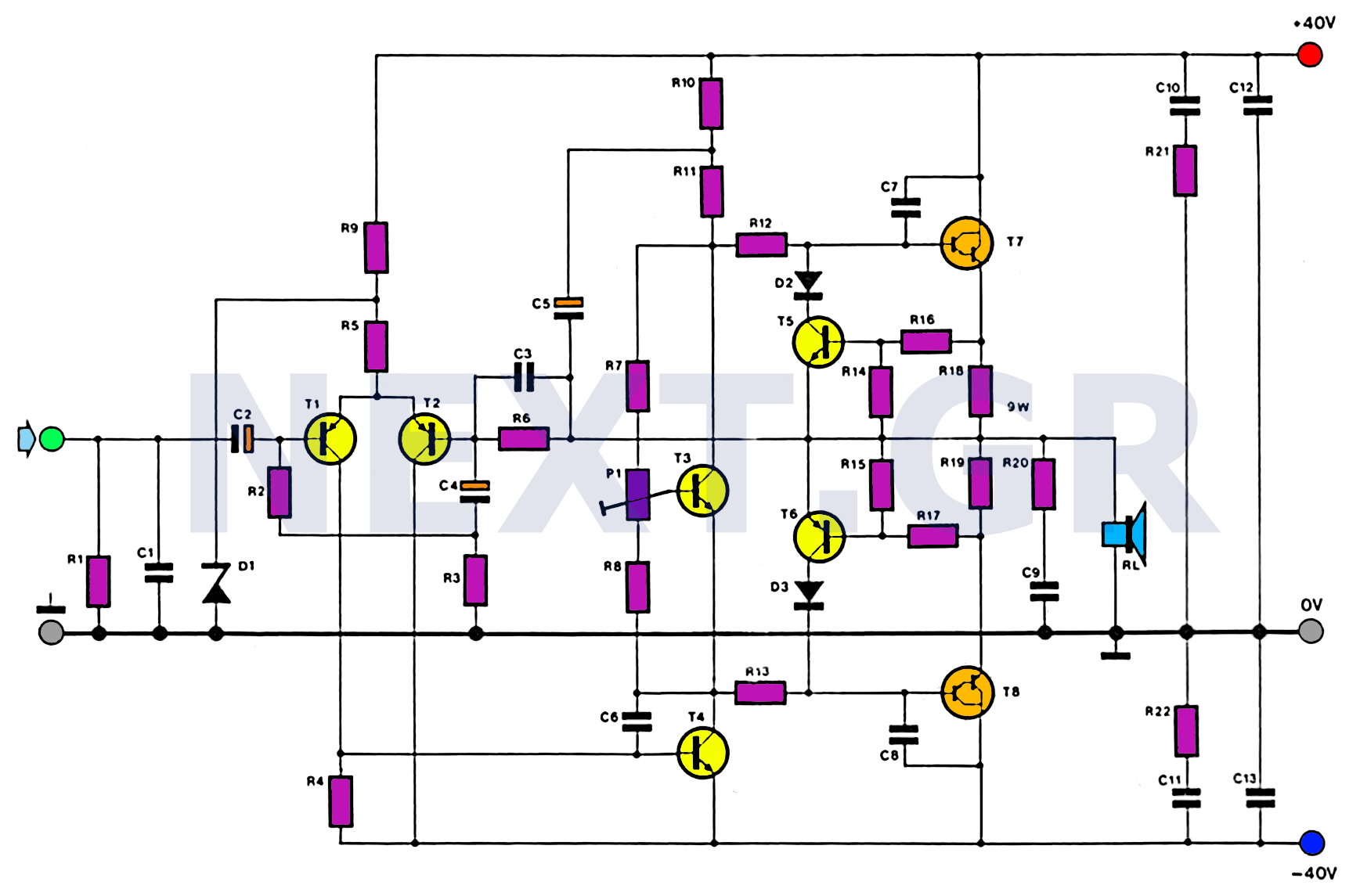
This amplifier is designed with the following specifications: distortion less than 0.1% at full power of 100W even at 20KHz, with power attributed to an extended bandwidth. The output transistors are protected against short circuits, and the power supply...
The circuit can be selectively tuned to two closely related tones. The selective frequency is determined by the values of the feedback circuit connected to the collector and base of Q1, which includes capacitors and resistors. When the specified...
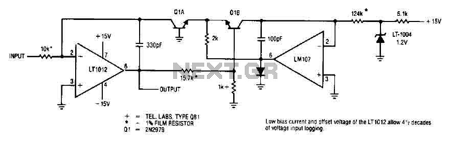
This simple logarithmic amplifier circuit uses the LT1012, which has a low bias current that allows for 4.5 decades of voltage input logging. Additionally, transistors that can be used in this circuit include the 2N2979. The logarithmic amplifier circuit designed...
Here is a simple schematic of a TV transmitter circuit, or video transmitter circuit, capable of broadcasting in the VHF range from 60 to 200 MHz. The input video source can be any CCD camera or VCR. The output...