
Very Low Frequency Multivibrator Circuit

In the context of electronic circuit design, a multivibrator is a circuit that generates a continuous output signal, which can be either square or pulse waveform. In this specific design, the implementation of Junction Field-Effect Transistors (JFETs) plays a crucial role in achieving the desired operational characteristics. JFETs are known for their high input impedance, which minimizes loading effects on preceding stages of the circuit, thereby maintaining signal integrity.
The design operates at a very low frequency of 0.15 Hz, which necessitates long time constants. This is achieved through the careful selection of passive components, such as resistors and capacitors, which determine the charging and discharging rates in the circuit. The high resistance values used in conjunction with larger capacitance values contribute to the extended time constants, allowing for the low frequency operation.
In practical terms, this multivibrator configuration can be used in applications where slow oscillation is required, such as in timers, oscillators for low-frequency signals, and other timing applications. The stability and reliability of the output signal at such low frequencies can be significantly enhanced by the use of JFETs, making this design advantageous for specific electronic applications. Proper simulation and testing should be conducted to ensure that the circuit meets the required specifications and performance criteria. The use of JFETs permits, high resistance and long time constants in this very low frequency multivibrator. The values shown are for 0.15 Hz operation.
Related Circuits

A tremolo circuit is a type of sound effect commonly utilized in guitar effect pedals. This effect is achieved by modulating the amplitude of an audio signal. The shape of the modulating signal can vary and may include square...
The 4017 traffic light circuit connects four legs to the green LED and two legs to the amber LED. This configuration raises the question of whether it could function with only one leg per LED. Each output is activated...
The LM358 consists of two independent, high-gain operational amplifiers in a single package. An important feature of this integrated circuit (IC) is that it does not require separate power supplies for the operation of each comparator, accommodating a wide...
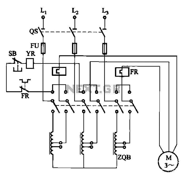
The circuit illustrated in Figure 3-47 involves a three-phase AC motor that is initially connected through a step-down autotransformer. To initiate operation, the power switch is closed, and the operating handle is pushed to the start position. Once the...

The objective of the project is to create a system that utilizes mobile technology to manage various home appliances based on signals sent from a mobile device. This innovative concept allows for the remote control of appliances through GSM...
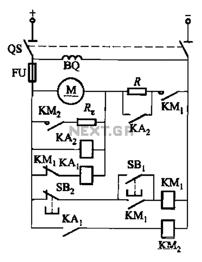
The circuit illustrated in Figure 3-196 features a starting resistance level and an undervoltage relay (KAz) that is controlled by the removal of the startup resistor. It also includes dynamic braking for shutdown purposes. The undervoltage relay (KAL) operates...