
VHF Antenna Amplifier Circuit Using BFT66 Transistor

The antenna amplifier circuit is designed to enhance signal reception for various applications, particularly in VHF and FM broadcasting. The use of the BFT66 transistor ensures high gain and low noise, making it ideal for weak signal environments. The common emitter configuration of the transistor allows for significant amplification of the input signal, which is crucial for effective antenna performance.
The L1 coil, with its specified inductance, plays a vital role in tuning the circuit to the desired frequency range. The flexibility in selecting L1 allows for optimization based on specific frequency requirements while maintaining performance across the designated spectrum. The L2 coil's air core design minimizes losses associated with magnetic materials, further enhancing the circuit's efficiency.
The placement of the PCB close to the antenna is essential for minimizing signal loss and interference. The metallic enclosure not only protects the components from environmental factors but also serves to shield the circuit from electromagnetic interference, which can degrade performance.
Powering the circuit with a 12-volt DC supply ensures compatibility with commonly available batteries, facilitating portability and ease of use. The low current consumption of under 10 mA contributes to the circuit's efficiency, making it suitable for battery-operated applications.
In summary, this antenna amplifier circuit design is a practical solution for enhancing VHF and FM signal reception. Its low noise characteristics, combined with the ability to operate across a wide frequency range, make it a valuable tool for various electronic projects and applications in radio and television broadcasting.Here`s a design circuit for very simple antenna amplifier electronic circuit project can be designed using this circuit diagram. This antenna amplifier electronic circuit can be used for a frequency range between 1 and 300MHz. This circuit antenna amplifier can be used for high frequency and VHF band (for radio and TV) and will provide a 22 dB gai
n. This antenna amplifier electronic project has a very low noise, under 1. 6dB. This is the figure of the circuit. This VHF, FM amplifier circuit is constructed based on the BFT66 transistor connected in common emitter connection. L1 coil has a 6uH value, but can be used any coil for high frequency (with a value between 5. 6 to 6. 8 u H). L2 coil is an air core type coil and it has 5-6 turns (10mm long and 5 mm diameter). For L2 coil can be used a 0. 25 mm Cuem wire. The pcb of this circuit must be placed near the antenna, in a small metallic box. This VHF antenna circuit must be powered from a 12 volts DC power supply circuit, you can use a 12 volt battery, because the current consumption of this circuit is very low under 10mA.
You can replace T1 transistor with some other UIF similar transistor type which have a very low noise factor. 🔗 External reference
Related Circuits
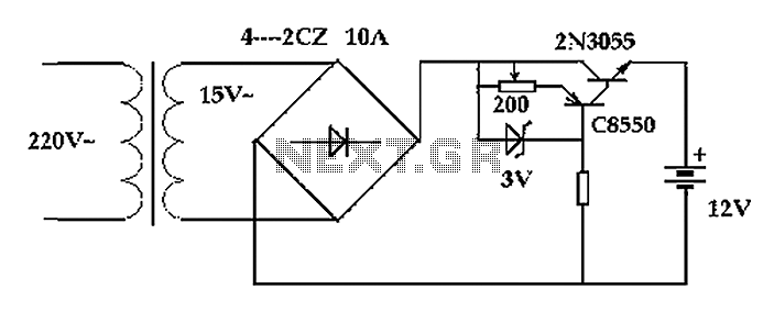
The circuit operates after a transformer, utilizing a bridge rectifier and conditioning for battery charging. The charging current transformer can be easily adjusted to provide approximately 12V at 100Ah battery charging. The required charging current is 10A, and a...
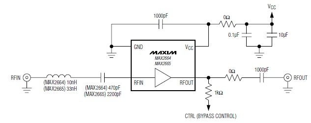
These devices feature a broadband low-noise amplifier (LNA) with an integrated bypass switch. The MAX2664 operates within the UHF frequency range of 470 MHz to 860 MHz, while the MAX2665 functions within the VHF frequency range of 75 MHz...
The motor control circuit depicted in the image utilizes the LM339 comparator among other components. When the input control signal is high (PWL), comparators A and A3 activate the power amplifier circuit, which consists of A4, VT5, and VT6,...
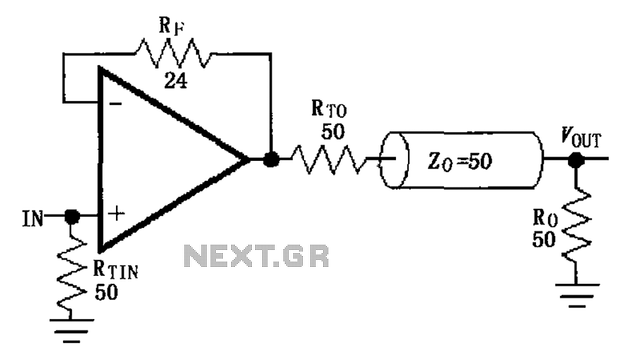
The MAX4450/4451 unity gain line is illustrated in the driving circuit. The MAX4450/4451 features internal compensation, a 24-ohm resistor in series within a feedback loop, along with capacitors and inductors that can reduce the Q value of the feedback...
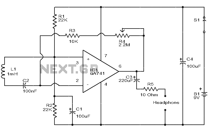
This is a simple circuit designed to detect electromagnetic radiation, including hidden wiring. It utilizes a 1mH inductor to sense the electric field. The induced voltage from the inductor is amplified by an operational amplifier (op-amp). An audio headset...
Have you ever witnessed the stairs to an upper story in your home transform into a waterfall? Or perhaps you have returned home to find your aquarium fish attempting to swim across the carpet? For your sake, it is...