
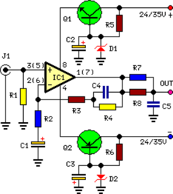
VHF-UHF Antenna Amplifier (Booster) 40-500MHz
 40-500MHz")
The described amplifier is designed to enhance signal reception in the VHF and UHF frequency ranges, making it suitable for applications such as television and radio signal amplification. The amplifier circuit typically consists of several key components: a transistor or operational amplifier, resistors, capacitors, and possibly inductors, which work together to boost the incoming signals.
In the schematic, the input stage often includes a matching network to optimize the impedance between the antenna and the amplifier, ensuring maximum power transfer and minimal signal loss. The amplifier stage is usually configured for gain, where the transistor or operational amplifier is biased to operate in its linear region, allowing it to amplify the weak signals received from the antenna.
Feedback mechanisms may be implemented to stabilize the gain and reduce distortion, while bypass and coupling capacitors are strategically placed to filter out unwanted frequencies and allow only the desired VHF and UHF signals to pass through. The output stage of the amplifier may include additional filtering to further refine the signal before it is sent to the receiver.
Power supply considerations are critical, as the amplifier must be powered adequately to ensure optimal performance. Depending on the design, the amplifier may operate on a single or dual power supply, with decoupling capacitors used to minimize noise from the power source.
Overall, this amplifier design is a vital component in enhancing the performance of VHF and UHF receivers, contributing to improved signal clarity and reception range.This amplifier has VHF (very high frequency) and UHF (ultra high frequency) response, you can use it for receiver booster for example. Here is the schematic. 🔗 External reference
Related Circuits
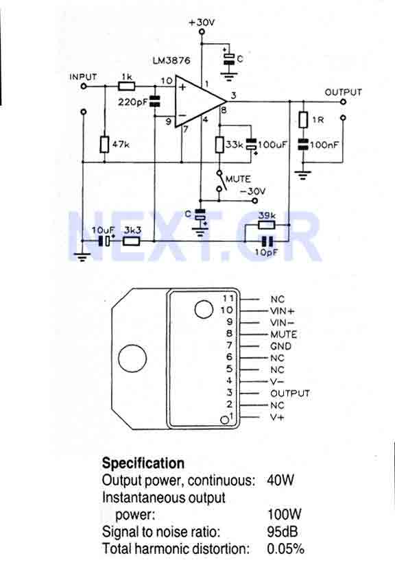
This Circuit is based on the LM3876. A 11-pin plastic package IC with high performance audio power amplifier, an output mute function which can be used to eliminate switch-on and switch-off "thumps" to the loudspeaker load. It is capable...
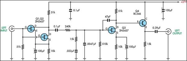
There are two types of preamplifiers for magnetic phono cartridges. The most common type includes an RIAA equalization network in the feedback loop, as described in the March 2002 issue of SILICON CHIP. The second type, previously used in...
Ultra-low EMI, mono and stereo, Class D audio power amplifiers deliver Class AB performance while maintaining Class D efficiency. Maxim's spread spectrum modulation (SSM) combined with third-generation EMI reduction techniques minimizes EMI radiation by decreasing the high-frequency components of...
This is a wideband shortwave (SW) antenna amplifier. The frequency range spans from 1 to 30 MHz, featuring a medium gain of 15 dB. The input stage utilizes an MPF102 transistor. The wideband shortwave antenna amplifier is designed to enhance...
In recent years, following the introduction of CDs, vinyl recordings have nearly disappeared. Nevertheless, a phono preamplifier remains useful for listening to old vinyl discs from a well-preserved collection. This simple yet efficient circuit designed for inexpensive moving-magnet cartridges...
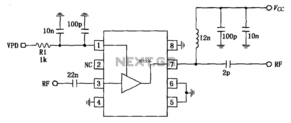
The circuit is based on an 880 MHz RF2347 low noise amplifier application. The radio frequency (RF) signal enters through input pin 3, and after amplification, the output is available at pin 7. The amplifier is directly coupled to...