
Voice-Modulated Pulse Fm Ir Transmitter

The circuit design begins with the 741 audio amplifier, which amplifies the audio signal captured from the microphone. The microphone should be of an amplified type to ensure sufficient signal strength for further processing. The output from the audio amplifier is then fed into an FM modulator, which modulates the audio signal onto a carrier frequency. This modulation process allows the audio signal to be transmitted over a longer distance using radio frequency waves.
A CMOS timer, configured as a voltage-controlled oscillator, is integrated to produce a square wave output. This output is essential for pulsing the LED, which emits infrared light. The frequency of the pulsing can be adjusted by varying the control voltage supplied to the timer, allowing for flexibility in the modulation frequency.
The pulsed output from the CMOS timer activates the LED, creating a pulsed IR beam that carries the FM-modulated audio signal. This IR beam can be detected by a compatible receiver, which demodulates the signal back into audio for playback.
Additionally, a booster circuit can be included in the design to amplify the IR signal, thereby increasing the effective range of the transmission. This can be particularly useful in applications where the distance between the transmitter and receiver is significant.
Overall, this circuit effectively combines audio amplification, frequency modulation, and infrared transmission to create a versatile communication system that can be utilized in various applications, including remote audio transmission and wireless audio systems. This circuit has a 741 audio amplifier, which is fed by a microphone (use an amplified type), an FM modulator, and a CMOS timer that acts as a VCO. The LED is pulsed with the timer output (the booster circuit can be used for increased range). This yields an FM-modulated, pulsed IR beam.
Related Circuits
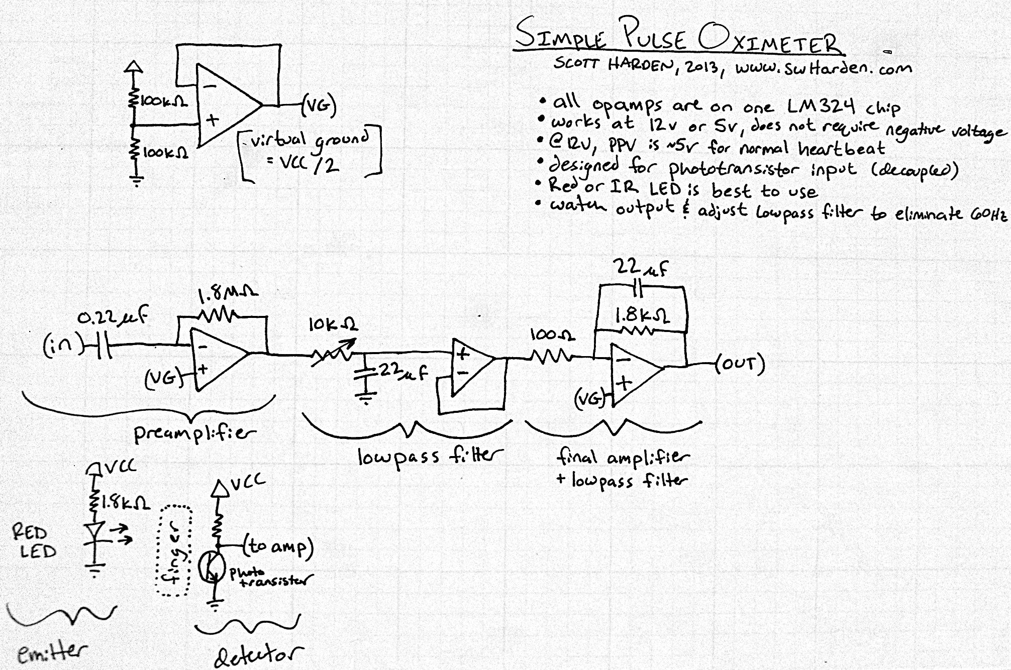
The input capacitor for the phototransistor at the bottom is responsible for feeding the operational amplifier (op-amp). However, the output from the phototransistor consistently remains between ground (GND) and the supply voltage (Vcc). The necessity for an input capacitor...
This circuit illustrates a 6-12 channel TV transmitter coupling circuit diagram. It is designed to stabilize the 10 P operation within the 6-12 channel range. The 6-12 channel TV transmitter coupling circuit is essential for ensuring stable transmission across multiple...
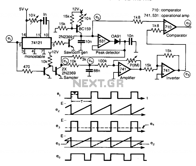
A circuit designed to multiply the width of incoming pulses by a factor that can be greater or less than unity is straightforward to construct. It features a single adjustable potentiometer for selecting the multiplying factor. This factor is...
Operating radio transmitters without a license is illegal in most countries, so caution is advised with transmitter circuits. This FM low-power circuit is designed to operate within the 87-108 MHz band II, providing a range of approximately 20 to...
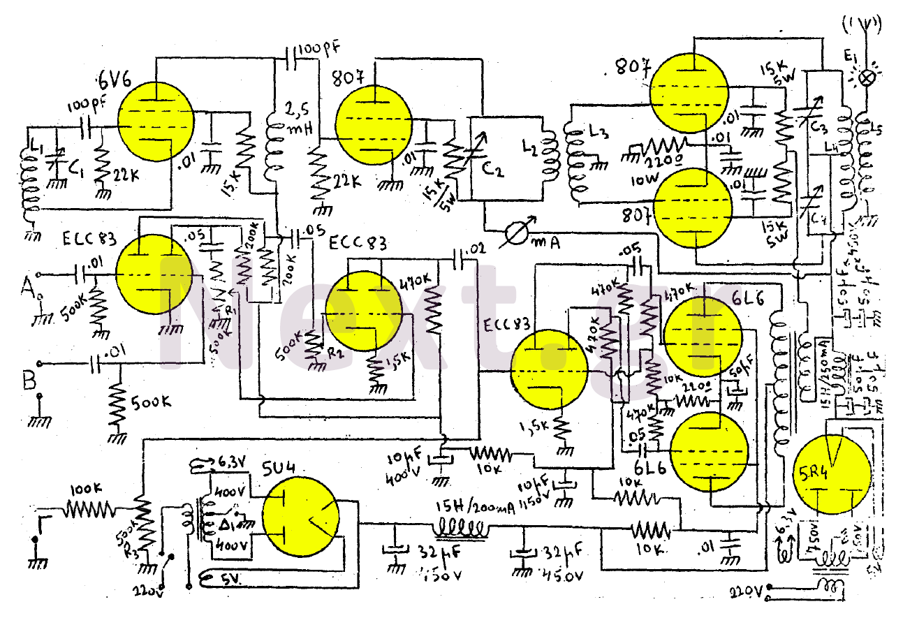
This transmitter consists of a 6V6 oscillator that excites an 807 buffer. The final stage includes two 807 tubes arranged in a Push-Pull configuration. The amplifier is built with three series-connected double-triodes (ECC83) and concludes with two 6L6 tubes...
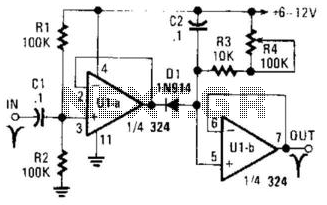
U1A functions as an amplifier that drives D2 and charges C2. U1B operates as a voltage follower. R3 and R4 set the amount of stretch applied to the input pulse. C2 is capable of being charged to handle varying...