
Voltage-Controlled Oscillator

The voltage-controlled oscillator (VCO) circuit described employs a combination of operational amplifiers and a MOSFET to create a frequency-modulated output based on a control voltage. The initial stage utilizes a 10 Hz sawtooth oscillator to generate the control voltage that dictates the frequency of the VCO. The integrator configuration of the first op-amp is crucial for transforming the control voltage into a linear ramp output, which oscillates between two defined voltage levels.
The voltage divider connected to the positive input of the op-amp ensures that the reference voltage is consistently set to half of the control voltage, allowing the op-amp to maintain a balance between its inputs. The use of a 100kΩ resistor is significant, as it regulates the current flow necessary for the operation of the circuit. When the MOSFET is engaged, it allows the current to flow through, thus influencing the capacitor charging dynamics. The 49.9kΩ resistor plays a pivotal role in determining the rate of change of current, effectively doubling the current flow due to its lower resistance.
The triangle wave output from the first op-amp is essential for the subsequent Schmitt trigger stage, which converts the analog triangle waveform into a digital square wave. The Schmitt trigger's hysteresis characteristics ensure that the output toggles cleanly between high and low states, providing a stable square wave signal that can drive the MOSFET. This square wave output is integral for applications requiring precise frequency control, such as in signal modulation or timing applications. The overall design illustrates a practical implementation of control voltage manipulation to achieve desired frequency outputs, showcasing the versatility of operational amplifiers and MOSFETs in electronic circuit design.This circuit is a voltage-controlled oscillator, which is an oscillator whose frequency is determined by a control voltage. A 10 Hz sawtooth oscillator provides the control voltage in this case; this causes the frequency to rise slowly until it hits a maximum and then falls back to the starting frequency.
The first op-amp is an integrator. A volta ge divider puts the + input at half the control voltage. The op-amp attempts to keep its input at the same voltage, which requires a current flow across the 100k to ensure that its voltage drop is half the control voltage. When the MOSFET at the bottom is on, the current from the 100k goes through the MOSFET. Since the 49. 9k resistor has the same voltage drop as the 100k but half the resistance, it must have twice as much current flowing through it.
The additional current comes from the capacitor, charging it, so the first op-amp must provide a steadily rising output voltage to source this current. When the MOSFET at the bottom is off, the current from the 100k goes through the capacitor, discharging it, so a steadily falling output voltage is needed from the first op-amp.
The third scope shows the output voltage; it looks like a triangle wave. The second op-amp is a Schmitt trigger. It takes the triangle wave as input. When the input voltage rises above the threshold of 3. 33 V, it outputs 5 V and the threshold voltage falls to 1. 67 V. When the input voltage falls below that, the output goes to 0 V and the threshold moves back up. The output is a square wave. It`s connected to the MOSFET, causing the integrator to raise or lower its output voltage as needed. 🔗 External reference
Related Circuits
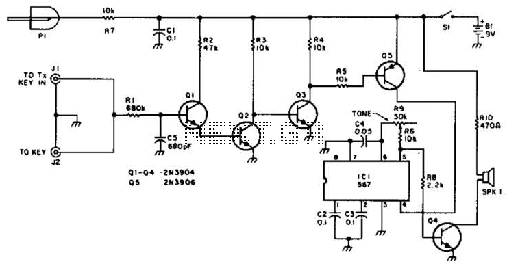
For use with low-power transmitters that require a positive keying voltage. The transistors Q1, Q2, and Q3 are configured as a switching amplifier. When the key is pressed, the collector of Q3 is pulled to ground, which activates Q5...
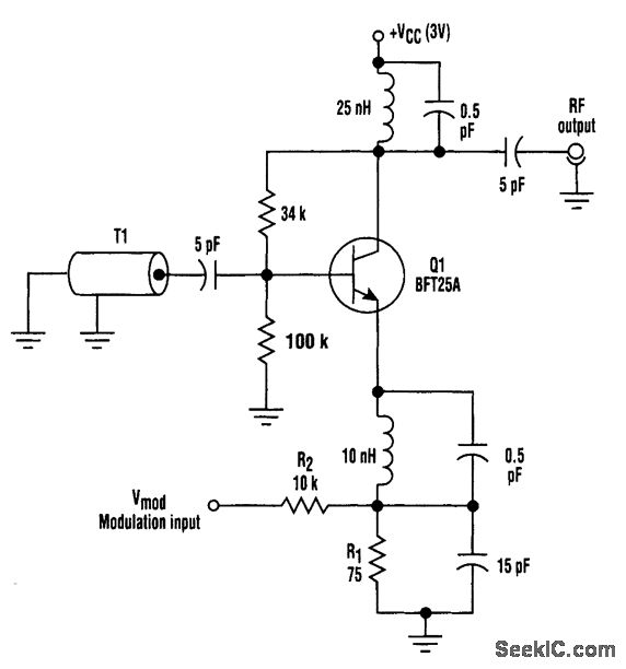
This circuit utilizes base-charging capacitance modulation instead of a varactor to frequency-modulate a high-frequency oscillator. This approach eliminates the significant voltage change required by a varactor, which can pose challenges in battery-powered systems with limited supply voltages. T1 serves...
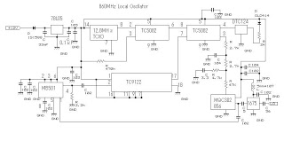
This 860 MHz Phase Locked Loop (PLL) oscillator circuit is designed for a 1200 MHz transverter's local oscillator with 435 MHz rigs. The oscillator circuit utilizes Toshiba PLL synthesizer ICs. The TC9122P is a user-friendly preset counter for determining...
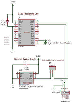
The SX 28 internal oscillator is not that fast, so an external oscillator can be hooked up to the processor as shown in the diagram to increase the operation cycles per second. The SX 28 microcontroller is designed with an...
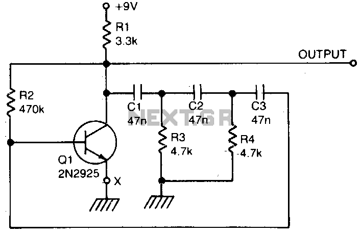
A single transistor is utilized to create a simple phase shift oscillator. The output produced is a sine wave with a distortion level of approximately 104. The purity of the sine wave can be improved by incorporating a variable...
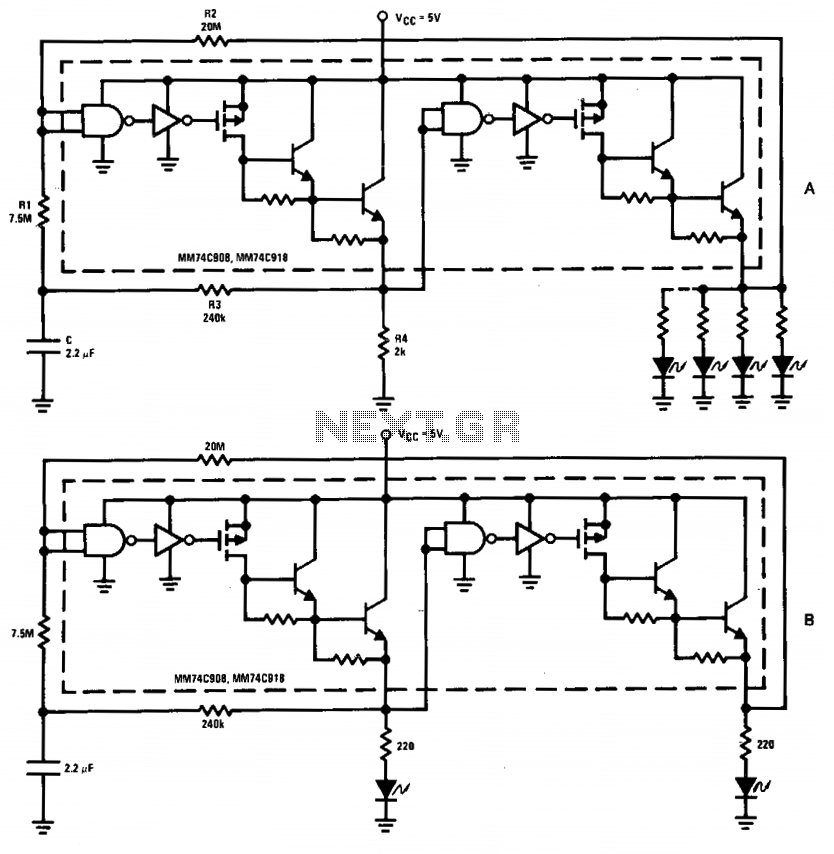
The driver in the package is configured as a Schmitt trigger oscillator (A), utilizing resistors R1 and R2 to create hysteresis. The inverting feedback timing components consist of resistor R3 and capacitor C, while resistor R4 serves as the...