
vusb

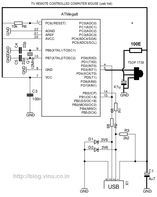
V-USB is a software-only implementation of a low-speed USB device for Atmel's AVR microcontrollers, enabling the creation of USB hardware with nearly any AVR microcontroller without the need for additional chips. It supports multiple endpoints, including one control endpoint, two interrupt/bulk-in endpoints, and up to seven interrupt/bulk-out endpoints. It is important to note that the USB specification prohibits bulk endpoints for low-speed devices; however, V-USB accommodates them to a certain extent. D1 and D2 serve as a cost-effective substitute for a low-drop 3.3V regulator chip, such as the LE33. Operating the AVR at higher voltages may exceed the common mode range of many USB chips. If the AVR is to be powered at 5V, it is recommended to incorporate 3.6V zener diodes at the D+ and D- lines to limit the voltage.
The V-USB implementation is particularly advantageous for projects requiring USB connectivity without the complexity and cost associated with dedicated USB hardware. The software stack provided allows seamless integration with various AVR microcontrollers, facilitating the development of devices such as input peripherals, data loggers, and other USB-based applications.
In terms of circuit design, the V-USB configuration typically includes a microcontroller, pull-up resistors on the D+ line, and the necessary diodes (D1 and D2) for voltage regulation and protection. The D1 and D2 diodes should be selected based on their forward voltage drop characteristics and power ratings to ensure they can handle the expected current load while maintaining the necessary voltage levels for USB communication.
The circuit should also incorporate bypass capacitors near the power supply pins of the AVR microcontroller to stabilize the supply voltage and filter out any noise that may affect USB communication. The use of proper PCB layout techniques is crucial for minimizing electromagnetic interference (EMI) and ensuring reliable signal integrity, especially in high-speed data transmission scenarios.
When designing the circuit, attention must be paid to the USB specification regarding signal integrity, especially for the D+ and D- lines, which should be routed as a differential pair to maintain the correct impedance and minimize crosstalk. Additionally, the overall design should account for the physical layout of the USB connector and ensure that the device complies with USB standards for mechanical and electrical characteristics.
In summary, V-USB provides a flexible and cost-effective solution for implementing USB functionality in AVR microcontroller-based projects, enabling designers to create a wide range of USB-enabled devices while adhering to USB specifications and ensuring reliable performance.V-USB is a software-only implementation of a low-speed USB device for Atmel`s AVR ® microcontrollers, making it possible to build USB hardware with almost any AVR ® microcontroller, not requiring any additional chip. Supports multiple endpoints: one control endpoint, two interrupt/bulk-in endpoints and up to 7 interrupt/bulk-out endpoints.
(Note that the USB specification forbids bulk endpoints for low speed devices, but V-USB supports them to some degree. ) D1 and D2 are a low cost replacement for a low drop 3. 3 V regulator chip, such as the LE33. Operating the AVR at higher voltages exceeds the common mode range of many USB chips. If you need to run the AVR at 5 V, add 3. 6 V zener diodes at D+ and D- to limit the voltage. 🔗 External reference
Related Circuits
While lying in bed and watching movies on a laptop, the idea arose that having a remote control would simplify the tasks of pausing, playing, fast forwarding, rewinding, adjusting volume, and playing the next track without needing to approach...