
Wailing alarm

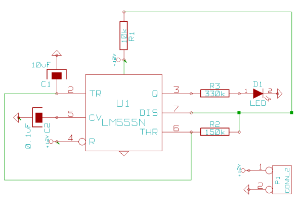
The circuit utilizes an integrated circuit (IC) configured as an astable multivibrator, specifically IC2, which serves to generate a low-frequency square wave. This square wave is characterized by a period of about 6 seconds, allowing for a gradual modulation of the output frequency. The ramp waveform produced across capacitor C1 is essential for creating a smooth transition in frequency, which is critical for simulating the characteristic sound of a police siren.
Transistor Q1, functioning as an emitter follower, amplifies the ramp signal while maintaining the same voltage level, allowing for effective coupling to the frequency modulation input of alarm generator IC1. The frequency modulation is achieved through resistor R6, which influences the extent of frequency variation based on the input signal from Q1. IC1, which is designed to generate alarm sounds, has a default center frequency of approximately 800 Hz, making it suitable for producing a siren-like tone.
The unique cycling behavior of the output signal is a result of the design of the astable multivibrator, which ensures that the frequency modulation follows a specific pattern. Initially, the output frequency starts low, gradually increases to a peak frequency over a duration of 3 seconds, and then decreases back to the starting frequency over the next 3 seconds. This continuous cycle creates the distinctive wailing sound associated with police sirens, making the circuit effective for alerting purposes in various applications. The design is versatile and can be adapted for different sound frequencies by adjusting component values, particularly those related to the timing of the astable multivibrator and the characteristics of the alarm generator.This circuit simulates the sound of an American police siren. IC2 is wired as a low frequency astable that has a cycling period of about 6 seconds. The slowly varying ramp waveform on Cl is fed to pnp emitter follower Ql, and is then used to frequency modulate alarm generator IC1 via R6. IC1 has a natural center frequency of about 800Hz. Circuit action is such that the alarm output signal starts at a low frequency, rises for 3 seconds to a high frequency, then falls over 3 seconds to a low frequency again, and so on ad infinitum.
Related Circuits

This infrared alarm barrier is designed to detect individuals passing through doorways, corridors, and small gates. The transmitter emits a beam of infrared light that is invisible to the human eye. When the light beam is interrupted by a...

Fire alarm circuit using an LDR (Light Dependent Resistor) as a flame sensor. It warns the user about fire accidents by detecting smoke produced during a fire. As smoke passes between an LED and an LDR, the amount of...
This page outlines how to create a simple theft deterrent that can be quite effective. The concept involves using a flashing red LED to indicate that the vehicle is protected. This device serves to safeguard the car from potential...
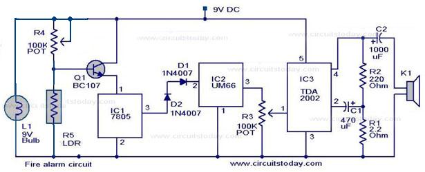
A simple fire alarm circuit utilizes a light-dependent resistor (LDR) and a lamp for smoke detection. The system operates by detecting smoke generated during a fire. An audible alarm is triggered when smoke is present. In the absence of...

In this circuit, the alarm is activated under four different conditions: 1. When light falls on LDR1 (located at the entry to the premises). 2. When light falling on LDR2 is obstructed. 3. When door switches are opened or...
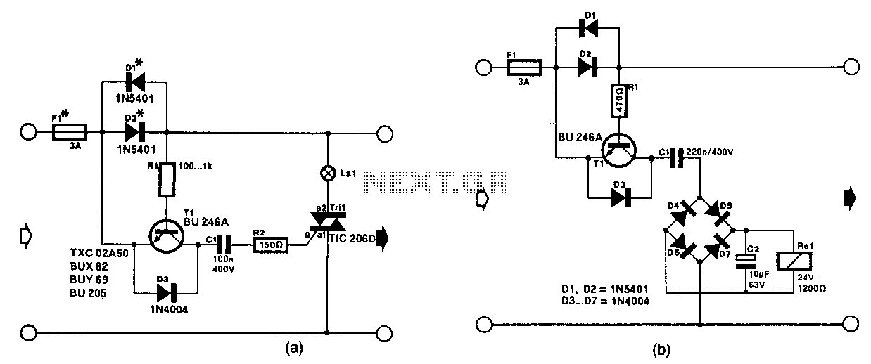
The circuit in Fig. 56-lla activates a signal lamp when it detects a line current consumption exceeding 5 mA and can handle currents of several amperes using suitable diodes in the D1 and D2 positions. Transistor T1 is activated...