
Water Alarm Circuit

The circuit consists of a 555 timer configured in astable mode, which continuously oscillates to produce a square wave output. The frequency of this output can be adjusted by selecting appropriate resistor and capacitor values connected to the 555 timer. In this application, the output frequency is set to around 1 kHz, which corresponds to a tone that can be easily recognized as an alarm sound.
The sensor component, typically a pair of conductive probes, is placed in a position where it can detect the presence of water. When water bridges the gap between the probes, it completes the circuit, triggering the 555 timer. The output of the timer is connected to a speaker or buzzer, which emits the audible alarm.
To ensure reliable operation, it is crucial to select the right resistors and capacitors for the desired frequency and to consider the sensitivity of the sensor. Additionally, incorporating a diode may be beneficial to protect the circuit from potential back EMF generated by the buzzer.
Power supply considerations should also be addressed, as the circuit typically operates on a low voltage, often supplied by batteries or a DC power source. Proper grounding and layout design will enhance the circuit's performance and longevity. Overall, this water detection alarm circuit provides an effective solution for alerting users to the presence of water through a simple yet efficient electronic design.This circuit gives out an alarm when its sensor is wetted by water. A 555 astable multivibrator is used here which gives a tone of about 1kHz upon detecting water. .. 🔗 External reference
Related Circuits
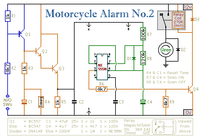
This circuit features an intermittent siren output and automatic reset. It can be operated manually using a key switch or a hidden switch, and it can also be wired to activate automatically when the ignition is turned off. By...
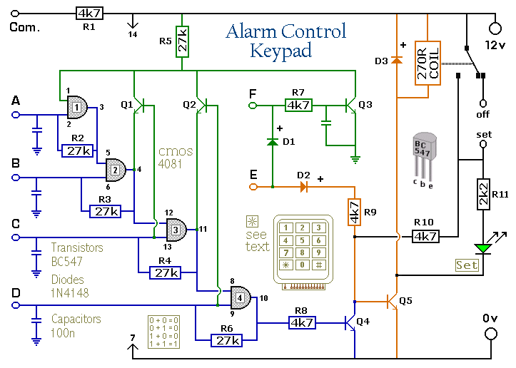
The Keypad must be the kind with a common terminal and a separate connection for each key. On a 12-key pad, look for 13 terminals. The matrix type with 7 terminals will NOT do. The Alarm is set by...

This circuit represents a negative resistance configuration. All previous circuits utilize RC time constants to achieve resonance. LC combinations can also be employed, providing good frequency stability, high Q factor, and rapid startup. In this circuit, a signal input...
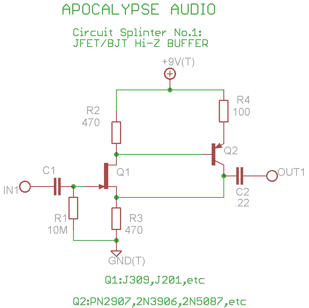
This is a common circuit often found in various resources, yet it appears to be less prevalent in stompbox applications. The circuit utilizes an NPN JFET DC coupled with a PNP BJT. The FET provides a significantly higher input...
This circuit is designed for use in a hi-fi showroom, allowing for the selection of different speakers to connect to a stereo amplifier for comparative listening. It can also serve similar applications where only one device from a set...
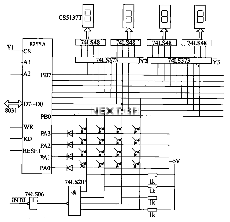
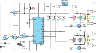
A 4x4 matrix keyboard system is designed for parameter settings, featuring numeric keys from 0 to 9 and function keys labeled A to F. The primary functions of the keyboard include completing parameter settings, selecting display modes, starting automatic...