
wein bridge sine wave oscillator lm101

The Wien Bridge Sine Wave Oscillator is a type of electronic oscillator that generates sine waves using a bridge circuit. The circuit typically consists of four resistors and two capacitors arranged in a bridge configuration, with the 2N3069 JFET acting as a variable resistor to control the gain of the amplifier. The oscillation frequency can be adjusted by changing the values of the resistors and capacitors in the bridge.
In this configuration, the LM103 Zener diode serves as a voltage reference, ensuring that the output amplitude remains stable. The feedback loop is crucial for maintaining oscillation; it must provide a gain that is equal to or slightly greater than one. The 2N3069 JFET, when operated in its linear region, adjusts its resistance based on the feedback voltage, dynamically stabilizing the loop gain.
The circuit operates by initially providing a small noise signal to the input. As the amplifier begins to oscillate, the feedback loop continuously adjusts the gain through the JFET until the desired amplitude is achieved. This method effectively minimizes distortion and ensures a clean sine wave output. The design's ability to produce a low distortion sine wave makes it suitable for applications in signal generation, testing, and audio synthesis.
To visualize the circuit, a schematic diagram typically includes the Wien Bridge configuration, highlighting the placement of the JFET and the Zener diode, along with the necessary passive components. The careful selection of these components and their arrangement in the circuit is essential for achieving optimal performance.This circuit is Wein Bridge Sine Wave Oscillator. The main problem in producing low distortion, constant amplitude sine wave to get the right loop gain amplifier. By using the 2N3069 JFET as variable resistor in the feedback loop voltage amplifier, this can be easily achieved.
LM103 zener diode provides a reference voltage to the peak amplitude si ne wave, are corrected and fed into the gate 2N3069, so many obstacles channels and, hence, the loop gain. Here is a schematic drawing: 🔗 External reference
Related Circuits
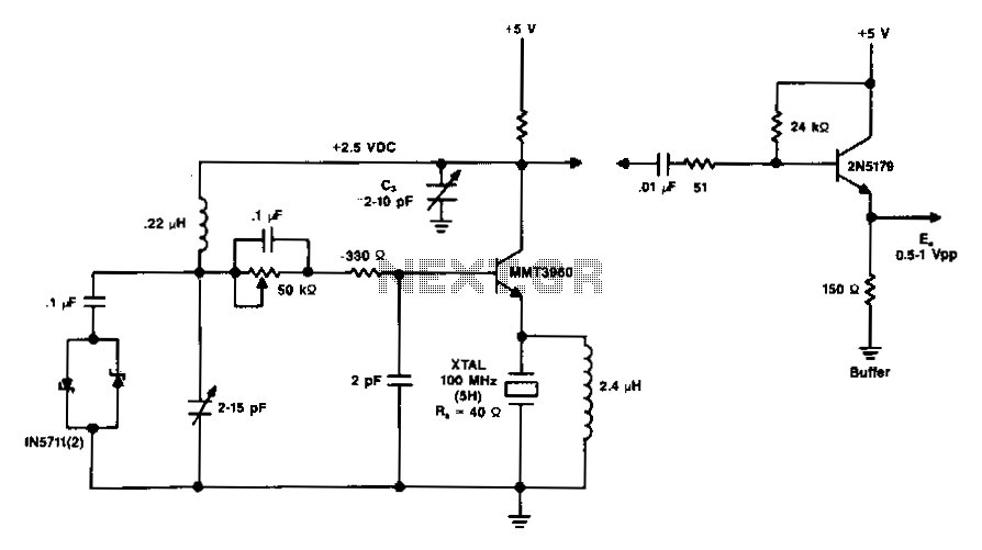
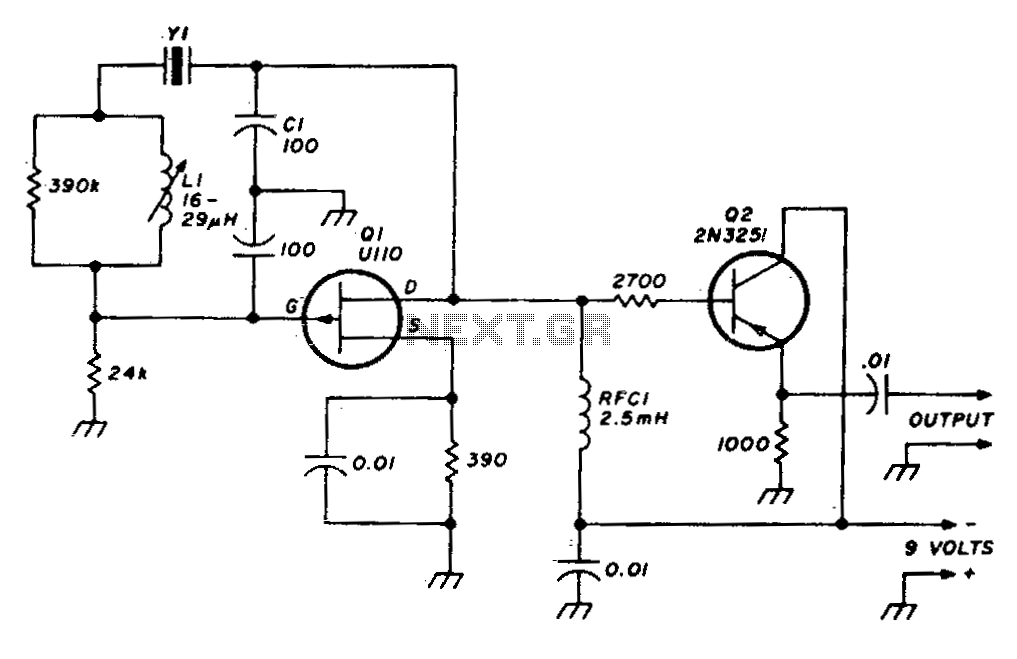
The diagram illustrates a 100 MHz oscillator functioning on the fifth harmonic. To preserve the transistor's gain, it is important to note the increase in the collector's load resistance, Rl, due to the rise in the quartz crystal's internal...
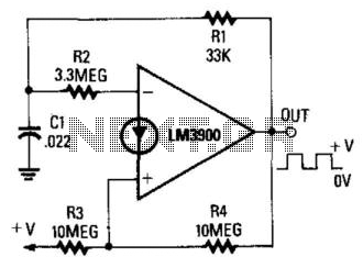
When the output is high, R3 and R4 are in parallel, and C1 charges through R1 until the current in R2 equals that at the non-inverting terminal. This action occurs when C1's voltage rises to 2/3 of the supply...
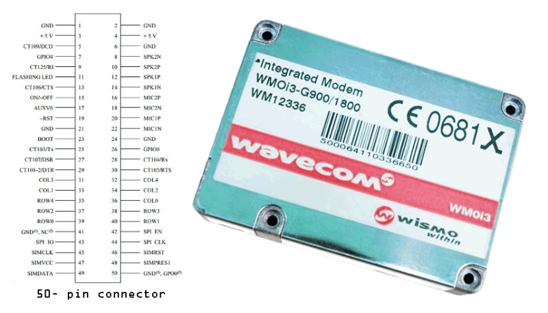
Modems are devices that connect remote devices to a computer or enable communication between multiple computers. While traditional modems typically use wired connections, the GSM modem described here operates wirelessly. It can link two computers, connect a computer to...
The circuit is a modified Colpitts oscillator, tuned with MV209 varactor diodes. The resonating inductor and the drain choke are selected by a rotary switch. 1N5711 Schottky diode, D, clamps the maximum positive voltage on the gate of oscillator...
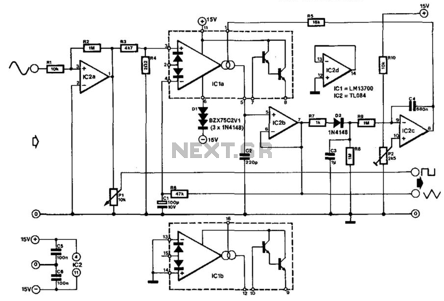
Many function generators utilize a rectangular waveform generator that comprises a Schmitt trigger and an integrator. The triangular signal generated by the integrator is subsequently transformed into a sinusoidal signal using a diode network. The converter described here operates...
A stable variable crystal oscillator (VXO) utilizing 6- or 8-MHz crystals employs a capacitor and an inductor to facilitate frequency pulling on either side of series resonance. The described circuit operates as a variable crystal oscillator, which is crucial in...