
When use Voltage divider in circuit analysis

In a circuit where resistors are connected in a Delta configuration, converting to a Wye configuration is often advantageous for simplifying calculations, particularly in series circuits. The conversion from Delta to Wye can be achieved using the following formulas:
\[
R_a = \frac{R_{12} R_{13}}{R_{12} + R_{13} + R_{23}}
\]
\[
R_b = \frac{R_{12} R_{23}}{R_{12} + R_{13} + R_{23}}
\]
\[
R_c = \frac{R_{13} R_{23}}{R_{12} + R_{13} + R_{23}}
\]
Where \( R_a, R_b, \) and \( R_c \) are the resistances in the Wye configuration corresponding to resistors \( R_{12}, R_{13}, \) and \( R_{23} \) in the Delta configuration.
Once the Wye resistances are calculated, the total resistance \( R_{total} \) in the series circuit can be determined by summing the individual resistances:
\[
R_{total} = R_a + R_b + R_c
\]
Using Ohm's Law, the output voltage across resistor \( R_2 \) can be calculated as follows:
\[
V_{out} = V_{in} \times \frac{R_2}{R_{total}}
\]
Given that \( V_{in} = 10V \), substituting the values will yield the desired output voltage. It is crucial to ensure that all resistances are in the same unit (ohms) for accurate calculations. The final output voltage can then be determined by plugging in the calculated resistances into the voltage divider formula.First I convert the Delta R2-R3-R4 to Y (wye), because the Voltage divider should be used in a series circuit so I tried to convert the delta to series, but that just work for find the total Resistance. so in this case $$V_{out} = V_{R_2}$$ I am using $$V_{in} = 10v$$, but I can`t figure out which should be the Total resistance in this case, I mean what is the value of
🔗 External reference
Related Circuits
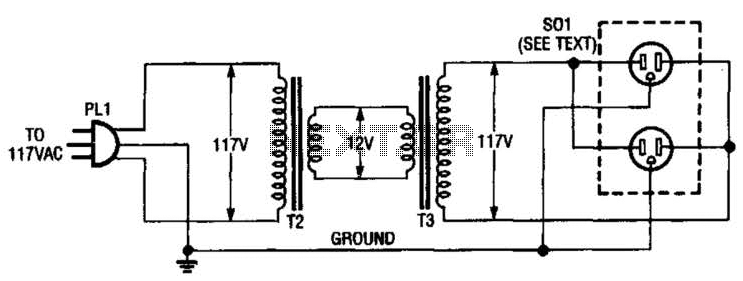
An isolation transformer for low-power applications (under 50 W) can be constructed using two 12-V filament or power transformers. This setup includes a standard duplex AC receptacle. It is important to utilize heavy-wire connections between the 12-V windings, as...
A 2 µF capacitor is charged to approximately 340 volts, and the discharge is controlled by a silicon-controlled rectifier (SCR). A Schmitt trigger oscillator (74C14) and a MOSFET (IRF510) are utilized to drive the low-voltage side of a small...
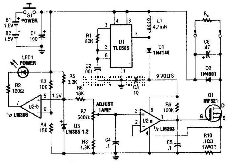
Useful for low-resistance measurements, this 1-A current source will produce 1 A in unknown resistance Rx. For best results, Rc should be less than 1 to 2, because only 3 V are available. Ul is a flyback converter to...

The circuit activates a light corresponding to the first button pressed in a "Who's First" game. Three stages are illustrated, but the circuit can be expanded to accommodate any number of buttons and lamps. The described circuit operates as a...
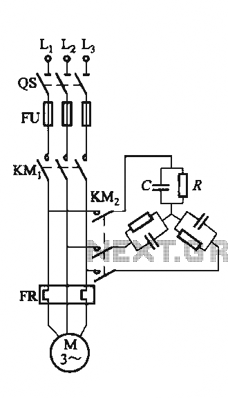
The circuit illustrated in Figure 3-151 consists of capacitor banks arranged in a specific configuration. Figure 3-151 (a) depicts capacitor banks connected in a shaped configuration, which is suitable for shaped or Y-connected motors. Figure 3-151 (b) shows Y-connected...
This controller consists of three pairs of LED sensors arranged in a 3G-bridge configuration. The driver is capable of operating three actuators, with the motors connected in a Delta configuration. The apexes of the delta are linked to the...