Wide-range-digitally-controlled-variable-gain-amplifier

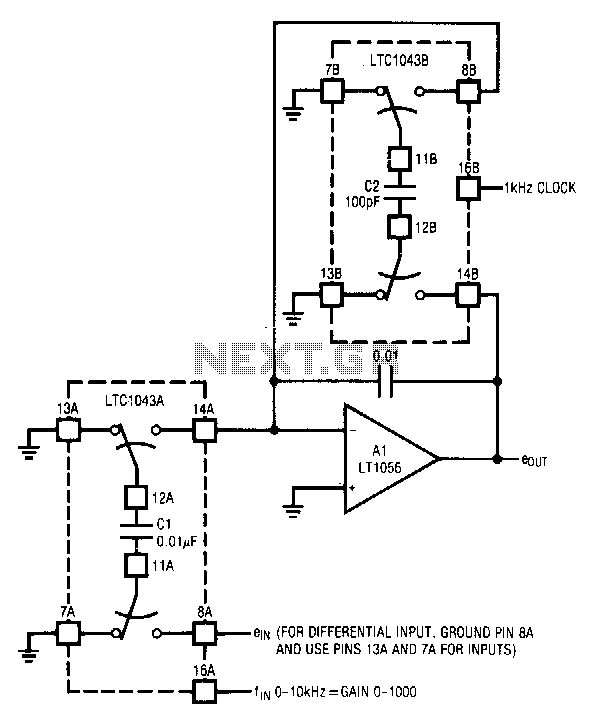
The circuit utilizes the LTC1043 in a variable gain amplifier configuration, which offers continuously adjustable gain, gain stability of 20 ppm/°C, and supports both single-ended and differential inputs. Two separate LTC1043 devices are employed in the design. The LTC1043B is continuously clocked by a 1-kHz source, which may also be supplied by a processor. Both LTC1043 devices operate as the sampled data equivalent of a resistor within the bandwidth defined by a 0.01 µF capacitor and the switched-capacitor equivalent feedback resistor. The time-averaged current delivered to the summing point by LTC1043A is determined by the input-derived voltage of the 0.01 µF capacitor and the commutation frequency at pin 16. Lower commutation frequencies yield smaller time-averaged current values, necessitating a larger input resistor, while higher frequencies require a correspondingly smaller input resistor.
The circuit design incorporates the LTC1043, a precision, low-drift, switched-capacitor technology component, which is pivotal in achieving the desired variable gain characteristics. The use of two LTC1043s allows for enhanced performance by separating the gain control and signal processing functions, facilitating greater flexibility in gain adjustment. The LTC1043B's continuous clocking at 1 kHz ensures that the signal processing remains responsive and stable, allowing for real-time adjustments to the gain based on input signal conditions.
The selection of a 0.01 µF capacitor is critical as it sets the bandwidth for the circuit, influencing the overall performance and response time. This capacitor, in conjunction with the switched-capacitor feedback resistor, forms a low-pass filter that determines the frequency response of the amplifier. The design must account for the trade-off between gain stability and bandwidth, as the gain stability of 20 ppm/°C ensures minimal drift with temperature variations, which is essential for precision applications.
The operational behavior of LTC1043A, in relation to the input voltage and commutation frequency, highlights the importance of selecting appropriate resistor values. The relationship between commutation frequency and input resistor size allows for tailored performance based on the specific application requirements. For instance, in scenarios where low frequencies are utilized, a larger input resistor is necessary to accommodate the lower time-averaged current, while higher frequencies can leverage smaller resistors for optimal performance.
Overall, this circuit exemplifies the application of advanced analog techniques to achieve precise control over gain in electronic systems, making it suitable for a variety of applications where signal integrity and stability are paramount.The circuit uses the LTC1043 in a variable gain amplifier which features continuously variable gain, gain stability of 20 ppm/°C, and single-ended or differential inputs. The circuit uses two separate LTC1043s. LTC1043B is continuously clocked by a 1-kHz source, which could also be processor supplied. Both LTC1043s function as the sampled data equivalent of a resistor within the bandwidth set by Al"s 0.01-I"F value and the switched-capacitor equivalent feedback resistor.
The time-averaged current delivered to the summing point by LTC1043A is a function of the 0.01-I"F capacitor"s input-derived voltage and the commutation frequency at pin 16. Low-commutation frequencies result in small time-averaged current values, and require a large input resistor.
Higher frequencies require an equivalent small input resistor.