
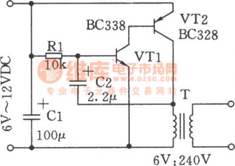
WIDE RANGE STAIRCASE GENERATOR

The circuit operates by utilizing a high input impedance to prevent loading effects that could distort the input signal. This characteristic is essential when interfacing with sensitive signal sources. The low output impedance ensures that the output can drive subsequent stages without significant voltage drop, maintaining signal integrity.
The staircase waveform is created through a charge and discharge cycle facilitated by diode D2 and capacitor C2. During the charging phase, the capacitor accumulates charge, and the diode allows current to flow in one direction, effectively boosting the voltage level at the output. The bootstrapping technique used here helps maintain a consistent output amplitude across each step of the staircase, which is crucial for applications requiring precise voltage levels.
The circuit's design is optimized for a 12-V input pulse, enabling it to generate 10 distinct voltage steps. Each step corresponds to a specific voltage level, allowing for controlled output that can be utilized in various applications, such as analog-to-digital conversion or signal processing. The values of the components used in the circuit are critical for achieving the desired performance and should be selected based on the specific requirements of the application.
In summary, this circuit provides a reliable method for generating a staircase waveform with minimal voltage droop and consistent output levels, making it suitable for various electronic applications requiring precise voltage control.Has high input impedance und low output impedance, to reduce droop in output voltage between pulses. Staircase is generated by pump D2-C2, which is boostrapped on output to maintain equal amplitude on each step. Circuit values shown give 10 steps with 12-V input pulse. -"Transistor Manual, " Seventh Edition, General Electric Co. , 1964, p 345. 🔗 External reference
Related Circuits
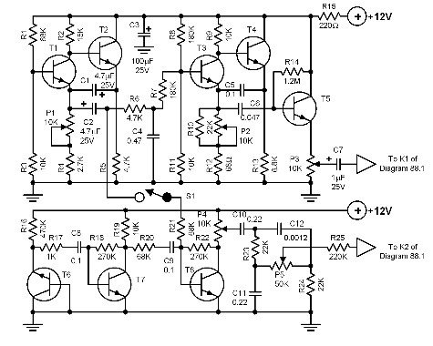
The construction of this complex circuit will yield the pleasure of generating nearly unlimited sound effects. The circuit is capable of producing a variety of sounds, ranging from the heavy chopping of helicopter blades to the delicate chirping of...
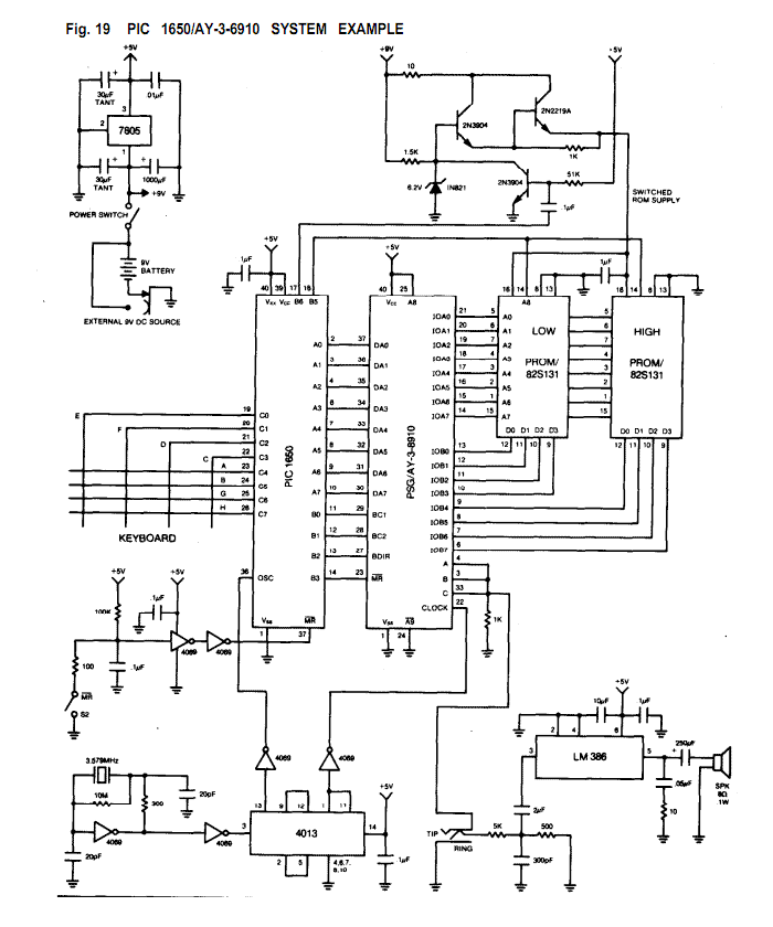
The AY-3-8910/8912 is a register oriented Programmable Sound Generator (PSG). Communication between the processor and the PSG is based on the concept of memory-mapped I/O. Control commands are issued to the PSG by writing to 16 memory-mapped registers. Each...
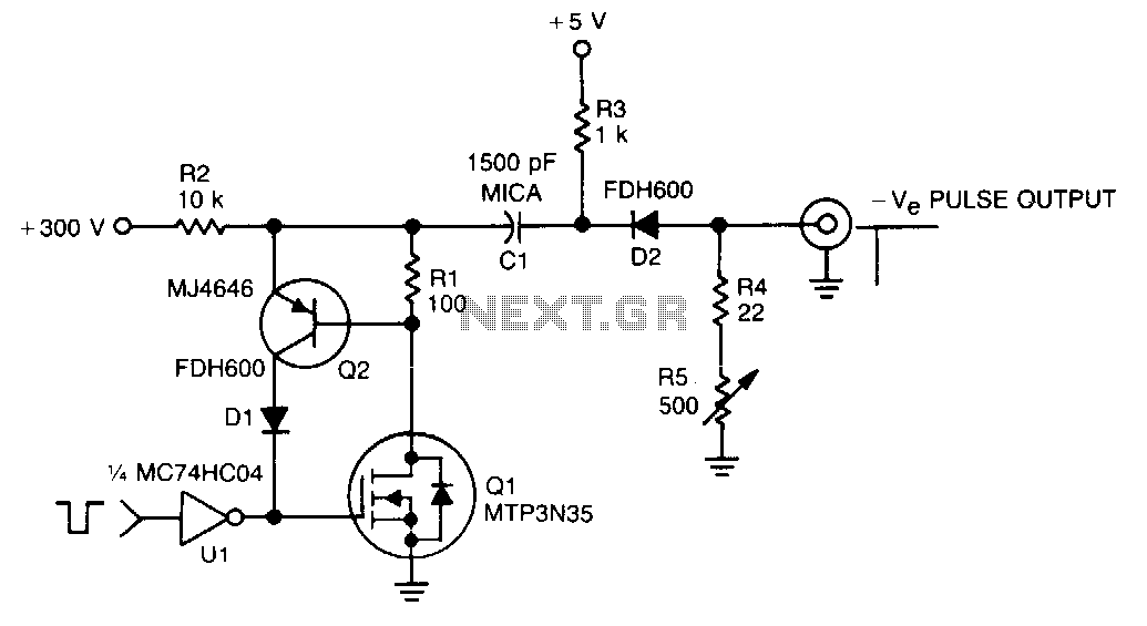
In this TMOS pulser, a negative-going pulse is applied to U1, a high-speed CMOS buffer, which directly drives the gate of Q1, an MTP3N35. If only a 100-V pulse is required, the MTA6N10 can be used. The pulse output...
A switch-mode power supply provides ±15V or ±12V at 0.5A output from a 4.5V to 12V input. The wide input voltage range allows flexibility to be powered from a regulated DC voltage. The switch-mode power supply (SMPS) described operates within...
The volt-ampere characteristics of a tunnel diode exhibit an S-shaped curve. The peak current point, referred to as point P, represents the maximum current, while the valley point, denoted as point V, indicates the minimum current. Key parameters of...
This rain sound effects generator circuit simulates the sound of rain and can be utilized in electronic music and radio shows. The noise source employs a germanium diode that is directly polarized and subsequently amplified by a single-stage amplifier...