
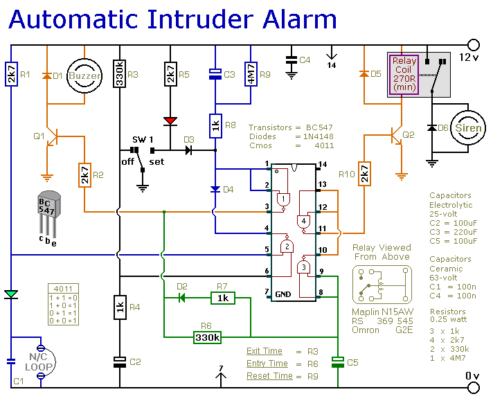
Wire Loop Alarm

The wire loop alarm circuit operates on a straightforward principle involving a closed-loop of wire that, when interrupted, triggers an alert. The core components of the circuit include a power supply, a resistor, a transistor, a siren (or relay), and the tripwire itself.
The tripwire is strategically placed in a doorway or hallway, creating a closed circuit. When an intruder breaks the wire, the circuit opens, causing a change in current flow. This change is detected by the transistor, which acts as a switch. The transistor is typically configured in a common-emitter configuration, where it amplifies the change in current to drive the siren.
The siren serves as the primary alert mechanism. In the basic configuration, a small siren is connected directly to the output of the transistor. However, for applications requiring a more robust alert system, the siren can be replaced with a relay. This relay can control larger external devices, such as industrial sirens or commercial alarm systems, enhancing the overall effectiveness of the alarm system.
The circuit should also include a resistor in series with the base of the transistor to limit the current flowing into it, ensuring that the transistor operates within safe limits. Additionally, a diode may be placed in parallel with the relay to protect the circuit from back EMF generated when the relay coil is de-energized.
For optimal performance, the power supply voltage must be chosen to match the specifications of the components used, particularly the siren or relay. Common supply voltages for such circuits are typically 9V to 12V, depending on the requirements of the siren or relay.
Overall, this simple wire loop alarm circuit provides an effective and low-cost solution for security applications, offering flexibility in alert mechanisms and ease of installation.This circuit is a simple wire loop alarm that can be used in doorways, hallways, or any other place the tripwire will be broken by intruders. The circuit has a built in siren, but it can be replaced by a relay to drive an external siren, commercial alarm, etc.
🔗 External reference
Related Circuits

This project involves a simple and cost-effective transmitter designed for hobbyists and home experimenters, capable of transmitting speech over a short distance. It functions as a cordless microphone, utilizing two integrated circuits from Maxim. The first IC, MAX4467, acts...

Have you ever witnessed the stairs to an upper story in your home transform into a waterfall? Or perhaps you have returned home to find your aquarium fish attempting to swim across the carpet? For your sake, it is...

This circuit generates a high-intensity sound force field inside a vehicle, which is painful enough to deter a thief from entering the car after the alarm switch is triggered by opening the door. The circuit produces a square-wave output...

This FM radio-controlled anti-theft system can be used with any device operating on a 6 to 12-volt DC power supply. The mini VHF FM transmitter is installed in the vehicle at night when it is parked in the driveway...

The circuit requires two transistors to drive a relay, which acts as a switch to activate a buzzer. Any number of normally-open switches may be applied. Mercury switches should be installed to ensure they close when the steering is...
This is a simple single-zone burglar alarm circuit. Its features include automatic exit and entry delays and a timed bell/siren cut-off. It is designed to be used with the usual types of normally-closed input devices such as magnetic reed...