
Wiring 2-Wire Intercom

A 2-wire intercom system is designed to facilitate communication over a limited distance, typically within buildings or residential areas. The system operates using two conductors, which serve both power and audio signals, thereby simplifying installation and reducing wiring complexity.
The basic components of a 2-wire intercom system include a master station and one or more slave stations. The master station is usually installed in a central location, allowing the user to initiate communication with any of the connected slave stations. Each slave station typically features a speaker and a microphone, enabling two-way communication.
The wiring configuration involves connecting the master station to each slave station using a pair of wires. The audio signals are transmitted over these wires, and the system often incorporates a power supply that feeds the necessary voltage to the stations.
In addition to basic communication functions, many 2-wire intercom systems may include additional features such as doorbell integration, volume control, and even video capability in advanced models. The installation process generally requires careful attention to the electrical specifications of the devices and ensuring that the wire gauge is suitable for the distance to be covered, thereby minimizing signal loss and ensuring clear audio transmission.
Overall, a 2-wire intercom system provides a practical solution for private communication needs, combining ease of installation with reliable performance.Wiring 2-Wire Intercom. According to Wikipedia, an intercom is a stand-alone electronic communications system intended for limited or private dialogue.. 🔗 External reference
Related Circuits
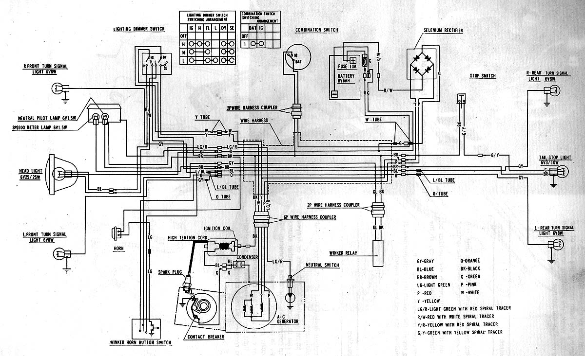
This circuit illustrates the electrical wiring diagram for the Honda S90, as detailed in the Haynes manual. It highlights the connections between various Honda components, including a fuse. The Honda S90 electrical wiring diagram serves as a vital reference for...
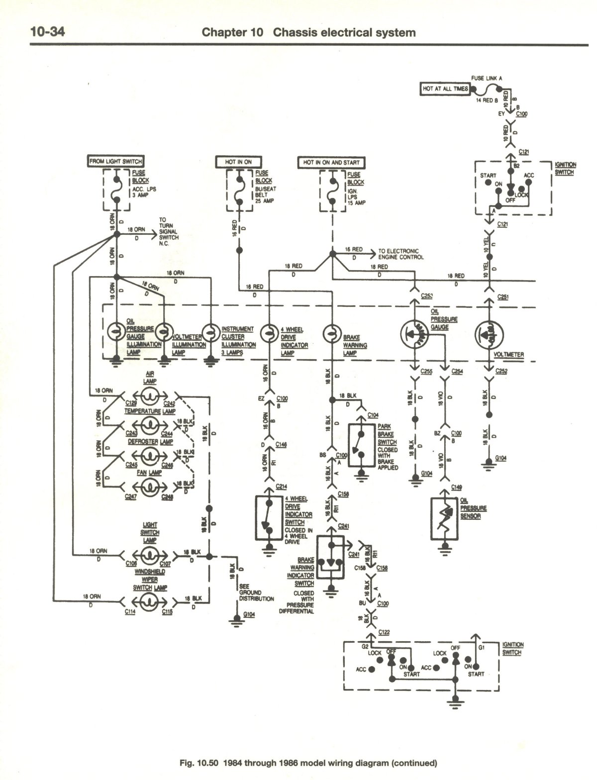
If there is no output at terminal 66 RED, it indicates a potential issue. The dash light dimmer may be set to the "OFF" position, or there could be significant corrosion on the wiper of the rheostat, preventing proper...
Toyota MR2 Exterior Lights Wiring Diagram Manual PDF Download. The Toyota MR2 Exterior Lights Wiring Diagram Manual provides a comprehensive guide for understanding the wiring configurations associated with the exterior lighting system of the Toyota MR2 model. This manual is...
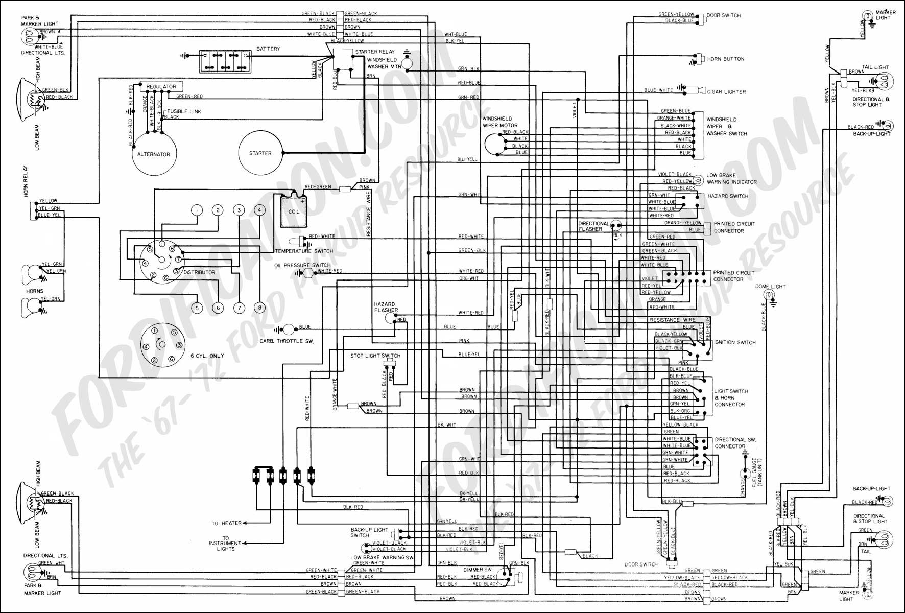
The vehicle is a 1968 Ford equipped with a 1972 engine. The original alternator has been replaced with a new unit. It has been suggested that reversing the polarity of the voltage regulator is necessary for the alternator to...
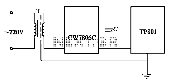
High-precision voltage regulator, isolation transformer with the correct wiring, and low-pass filter to enhance the electrical noise immunity of the source portion. The wiring in Figures 20-48 and 20-49 is illustrated in the figures. Chokes (L1, L2) should have...
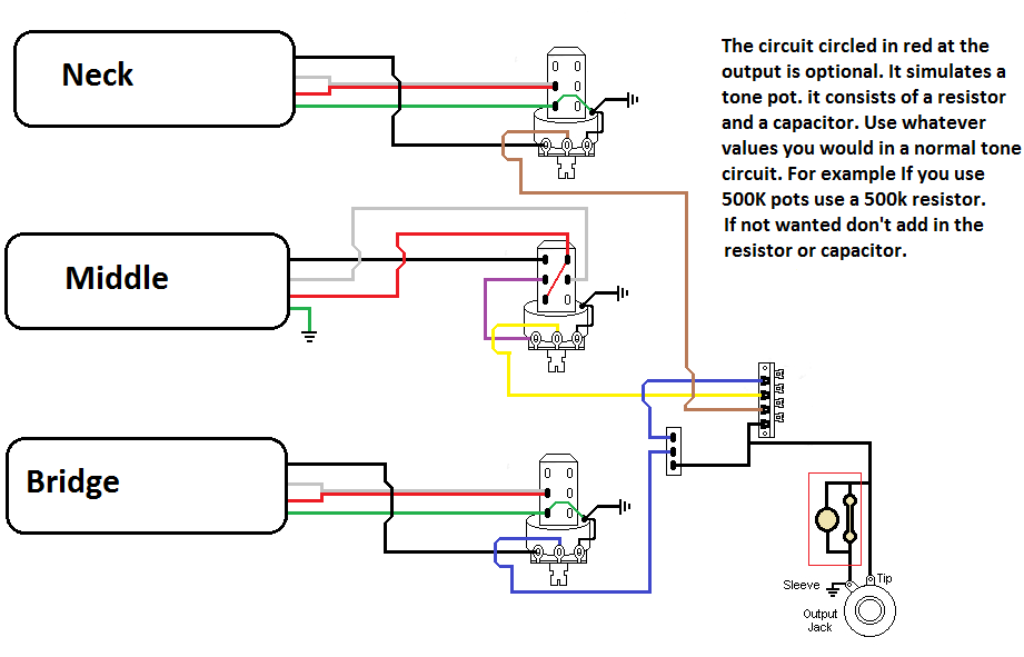
The pickups are connected to individual volume controls that feature push/pull functionality for coil tapping. They are routed to a 5-way switch before reaching the output jack. Additionally, a switch is desired to control the bridge pickup's activation when...