
XR400
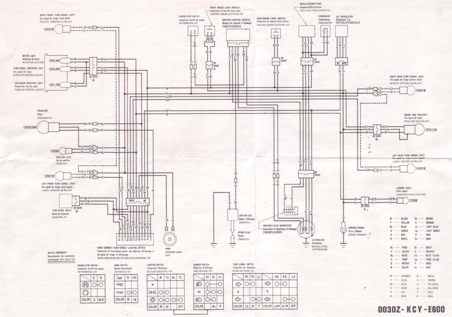
The bike will be used for long trips, off-roading at night, and dual sport riding, necessitating good headlamps, indicators, and an accessory socket. A 12V 10AH battery has been fitted to the bike, mounted on two custom lugs welded to the subframe. The battery connects to the regulator rectifier using green and black wires in place of the condenser near the headstock. The battery appears to charge from the alternator correctly, as it has not run flat yet. The stator is an upgraded 200W 3-phase unit. The headlamp in use is a Trailtech X2, featuring separate lamps for main and dipped beam. A 50W dipped halogen and an HID main beam are utilized, with a common ground wired to the battery negative. The high and low beam wires are routed through SPST relays that connect the positive directly to the battery. The relays are activated via the handlebar switch to ensure that the high current circuit for the lights is not part of the original wiring harness. To switch the relays on or off, a power source from the headlight switch is required, which must be 12V DC and available when the bike is not running. The White/Yellow wire, originally running from the alternator through the regulator to the handlebar switch, has been disconnected and spliced into a +12V DC wire from the battery. This system functions correctly, allowing the lights to be turned on when the bike is not running, and selecting high or low beam on the switchgear activates the relays and changes the headlight beam. LED indicators are installed with the appropriate relay; however, after modifications, the indicators ceased functioning when the headlight is on. The indicators work when the headlight is off, but neither works with sidelights selected. After examining the wiring diagram, it was found that the positive wires for the front indicators were incorrectly spliced into the rear indicator wires (orange/white and light blue/white). These were corrected and wired into the appropriate bullet sockets (orange and light blue), but the front indicators still do not operate in any lighting switch position. Additionally, the tail light and brake light are brighter when sidelights are selected than when all lights are on, despite the headlight being powered directly from the battery. The tail light is an LED cluster bulb, drawing minimal wattage. The battery has a maximum discharge rate of 40A.
The electrical system described involves multiple components working together to provide lighting and signaling functionality for the bike. The 12V 10AH battery serves as the primary power source, providing the necessary voltage and current to the lighting system. The upgraded 200W 3-phase stator ensures adequate power generation, allowing the battery to remain charged during operation.
The use of a Trailtech X2 headlamp, which incorporates separate lamps for main and dipped beam, enhances visibility during night rides. The decision to utilize SPST relays for the high and low beam operation is a strategic choice to isolate high current paths from the original wiring harness, thereby reducing the risk of overheating and potential damage to the existing electrical system. The relays are activated by a handlebar switch, allowing the rider to control the beam selection without risking the integrity of the original wiring.
The modification of the White/Yellow wire to splice into a +12V DC source from the battery is significant, as it enables the headlight switch to power the relays even when the bike is not running. This design choice facilitates the use of lights without draining the battery excessively when the engine is off.
The issue with the indicators not functioning correctly when the headlight is on may stem from incorrect wiring or insufficient power distribution. The previous splicing of the front indicators into the rear indicator wires suggests a potential oversight in the original wiring configuration. The corrective action taken to rewire the front indicators into their designated sockets is appropriate; however, the non-functionality following this adjustment indicates a possible fault elsewhere in the circuit, such as a poor connection, ground issue, or relay malfunction.
The observation regarding the tail light and brake light brightness when sidelights are selected versus when all lights are on is peculiar. This could be attributed to variations in voltage drop across the circuit, possibly due to the configuration of the wiring or the characteristics of the LED tail light. Further investigation into the wiring integrity and voltage measurements at various points in the circuit may be necessary to diagnose this anomaly effectively.
In summary, the described electrical modifications to the bike's lighting system present a complex interplay of components that require careful attention to detail in wiring and configuration. It is recommended to methodically troubleshoot each segment of the circuit, ensuring all connections are secure and that the system operates as intended under various conditions.I will be using the bike eventually for quite long trips, off roading at night and dual sport riding, so the bike needs good headlamps, indicators and an accessory socket. To this end, I fitted the bike with a 12v 10AH battery, on two custom lugs welded to the sub frame. The battery connects to the regulator rectifier green and black wires in place of the condenser up near the headstock.
As far as I can tell so far, the battery charges from the alternator ok, as it hasn`t run flat yet. The stator is an upgraded 200w 3 phase one. The headlamp I am using is a trailtech x2, with separate lamps for main and dipped beam. I`m running a 50w dipped halogen, and an HID main beam, so I have a common ground for both wired to the battery negative, and the wires for HI and LO are wired through SPST relays running the positve direct to the battery. The relays are switched via the handlebar switch, so that the high current circuit for the lights is not part of the original wiring harness.
To make the relays switch on or off, they needed a source of power from the headlight switch, and this source needed to be 12v dc and available when the bike was not running, so I took the White/Yellow wire that originally runs from the alternator, through the regulator, and into the handlebar switch, and disconnected it. I then spliced the wire from the switch into a +12v DC wire from the battery. This system in itself works, in that with the bike not running, I can turn the lights on, and selecting HI or LO on the switchgear triggers the relays, and changes the headlight beam.
I have led indicators fitted, with the correct relay, and before I did any of this, and the headlight was powered by AC from the stator, the indicators worked perfectly. However once I had done all this, the indicators stopped working when the headlight was on. If i turned the headlight off with the light switchgear, by flicking the 3 position switch that swaps between off, sidelights, and all lights to off, the indicators worked.
If I selected sidelights, neither worked, and if I selected all lights on, the headlight works, but the indicators don`t. After looking closely at the wires and the wiring diagram, I noticed that the positive wires for the front indicators were spliced into the wires for the rear indicators, ie.
orange/white and lightblue/white. I removed them and wired them correctly into the empty bullet sockets they are meant to go into ie. orange and light blue. However, once I had done this, the front indicators do not work at all, in any lighting switch position, which is why i suspect the previous owned had spliced them into the wires for the rear ones in this way. The other strange issue I notice is that at the rear of the bike, the tail light and brake light are much brighter when I have sidelights only selected, than when I have all lights selected.
I cannot see why this would be, if the headlight is powered directly from the battery, and the handlebar switch is only providing a tiny current to trigger the relays. The tail light is an LED cluster bulb, so is only drawing a very small wattage. The battery, as I said is a large 12v 10ah one, with a maximum discharge rate of 40A. I bet a lot of you reading this are thinking, man, what a mess. Thats exactly how I`m feeling as well. I think I just don`t really have enough knowledge of electrics to sort it, but I can`t pay a garage or electrician to do it either.
Can anyone make some suggestions or point me in the right way I`m at a total loss Well, It looks like nobody wants in on this, so I`ll try to help with some things to think about. Now you under stand that I`m in Texas, and even though 🔗 External reference