
Zener diode tester

This circuit operates as a high-voltage zener diode testing apparatus, featuring a robust design that incorporates safety measures to mitigate risks associated with high voltage. The primary components include two rectifiers that convert the AC input voltage into a DC output, and capacitors that store and stabilize the voltage levels. The use of resistors R4 and R5 is critical in controlling the output current, ensuring that the circuit remains within safe operational limits while allowing for effective testing of zener diodes.
The push-button switch provides an additional functionality to increase the current output, which is particularly useful when working with zener diodes that require higher test currents to function correctly. The output configuration with alligator clips facilitates easy connection to both the zener diode under test and a multimeter, allowing for real-time voltage readings.
Safety is a paramount concern with this circuit, as indicated by the inclusion of discharge resistors and a neon lamp for voltage indication. The resistors R1, R2, and R3 serve to safely discharge the capacitors, preventing accidental shocks when the circuit is not in use. The neon lamp acts as a visual indicator of high voltage, ensuring that users are aware of the circuit's status before attempting to interact with it. Overall, this circuit provides a reliable and efficient means of testing zener diodes, with necessary precautions in place to protect users from high voltage hazards.This is a circuit to test zener diodes. It hooks up to a 120V AC line and boosts the output voltage to over 300V allowing you to test zener diodes of any voltage. The circuit also has a push button switch to triple the current, if needed. The output is attached to 2 pairs of alligator clips. One pair is to attach to the diode. The second pair is to attach to a multimeter. The voltage across the diode is show on you multimeter. It should be noted that this circuit could be dangerous. It is tied directly to an AC line, and has an output of 300V. The output has resistors on each line, which limits the current making it a bit safer, but will still give you quite a shock. This circuit uses the two rectifiers and capacitors to boost and rectifies the AC input voltage to about 320V DC.
R4 and R5 are relatively large, and limit the output current to a small amount. So when you attach the zener diode it creates a shunt circuit, and the output voltage is set by the zener diode. R4 and R5 are relatively large, and limit the output current to a small amount. With a low voltage diode the max current is about 4mA. If you press the push-button the current is tripled. If the zener diode is large, the current will be very low, perhaps too low, so you may need to used the current tripler button.
320V is a high voltage and can be dangerous. So its important to lower the voltage to a safe level before you touch the contacts. R3 is used to discharge the bottom capacitor, and R2 is used to quickly discharge the lower capacitor when power is switched off. R1 is used to discharge the top capacitor and the neon lamp discharges the top capacitor when its voltage is above 80V.
So when the switches are turned off the bottom capacitor quickly discharges and the output voltage is almost instantly lowered to around 160V. The upper capacitor discharges more slowly. It takes about 2-3 seconds to lower to 80V and the lamp turns off, and it takes about 7 seconds to drop to 10 Volts.
But when the lamp turns off its safe to touch, and add/remove the diode. 🔗 External reference
Related Circuits
Most circuits utilize a 5 V regulated power supply for microcontrollers and sensors, as 8-bit microcontrollers operate efficiently at this voltage. The 5 V supply is adequate for powering white LEDs, thus the specific voltage requirements of individual LEDs...
A few weeks ago, it was noted that IKEA offers a set of color-changeable LED strips. There has been a search for an effective method to provide... The color-changeable LED strips from IKEA are designed to offer flexibility in lighting...
This is a convenient design for a transistor tester. The advantage of this circuit is that transistors can be tested without actually doing the circuit soldering. The tester uses two ICs: an NE 555 timer and a CMOS IC...
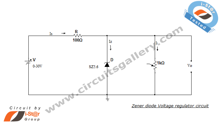
A Zener diode regulator is a fundamental electronic circuit valuable for hobbyists. This circuit provides a regulated output voltage, suitable for biasing other circuit components. The Zener diode operates in the reverse breakdown region, maintaining a nearly constant voltage...
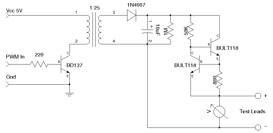
A simple Zener diode tester circuit, when combined with a PWM generator, can be utilized to measure the breakdown voltage of Zener diodes. More generally, it can also measure the breakdown voltages (e.g., BVceo, BVcbo) of BJTs (Bipolar Junction...
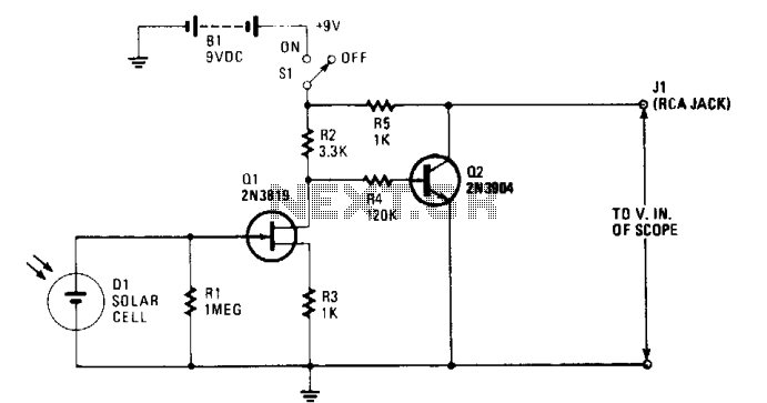
The solar cell is connected to the input of the field-effect transistor (FET), Q1, allowing it to generate a positive DC voltage at the gate when illuminated by light through the open shutter. This illumination reduces the negative gate-source...