
555 multi-temperature test circuit configuration
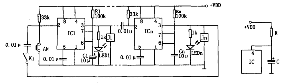
The multi-channel temperature measurement circuit utilizes a 555 timer configured in a monostable mode to create time delays for sequential temperature readings. The operation begins with the pressing of a button, which triggers the 555 timer (IC1) to generate a high output signal. This signal energizes relay J1, activating the selected thermocouple channel and illuminating LED1 as an indicator of the active measurement.
The charging process of capacitor C1 through resistor R1 is critical in establishing the timing intervals. The time delay (td) for each measurement cycle is calculated based on the formula td = 1.1R1C1, allowing for precise control over the duration of each channel's activation. The circuit's design ensures that as the voltage across C1 reaches 2/3 of the supply voltage (VDD), the 555 timer resets, generating a low output signal. This low signal is coupled through a 0.01 µF capacitor to trigger IC2, which activates the next thermocouple in the sequence.
In scenarios where switch K1 is engaged, the circuit can continuously cycle through the thermocouples, providing real-time temperature measurements across multiple channels. The design incorporates an initial flickering of LEDs during power-up, which can be mitigated by implementing an R-C network. This network stabilizes the reset state of the 555 timer, preventing erratic behavior and ensuring a smooth transition into the measurement phase.
Overall, this multi-channel temperature measurement circuit is an effective solution for applications requiring simultaneous temperature monitoring across various points, with built-in visual indicators for operational status and enhanced accuracy through careful timing control.As shown in Fig multi-channel temperature measurement circuit. The test circuit consists of a core consisting of 555 one-shot delay circuit. When the button i s pressed AN, IC1 (555) due to the occurrence of low feet set, high pin output relay J1 pull, the corresponding thermocouple channel is turned on. Meanwhile, LED LED1 lights. By R1 and capacitor C1 is charged, when the charge voltage on C1 to make foot potential reaches 2/3VDD, the 555 reset occurs, low back pin output by 0.01 mu F after capacitive coupling pin was low so IC2, IC2 occurs is set.
Output level corresponding turns on the second thermocouple, repeat the process, so in turn trigger, multi-channel temperature testing. If the circuit closes the switch K1, the cycle can be detected, and each stage of the measurement time (delay time) is td 1.1R1C1, icon parameter corresponding to a delay of about one second.
Taking measurements at the same time, LED lights, for detection indication. On the circuit diagram (a), when the power-up may occur a few light-emitting diode LED flicker at the same time, therefore, can be used as shown in (b), improved circuit. After accessing R, C network, when turned on, since the C voltage can not change suddenly, so that 555 (Ic) reset terminal ( feet) in forced reset state, pin output low, the capacitor C is charged with the conduct, feet potential gradually rises when foot potential rise to the high level, Ic at all levels in the timed waiting state, thereby improving the accuracy of the test circuit.
This circuit is used when the multi-channel temperature testing, switch the thermocouple corresponding channel.
Related Circuits

To utilize this facility, the calling subscriber must first dial the standard phone number of the intended recipient. Once the call is connected, the calling party does not hear a ring-back tone. The calling subscriber must then press the...
This house alarm circuit features both open and closed loop sensors and includes a self-shutdown function. The delay after triggering can be adjusted between 1 minute and 12 minutes, while the delay before triggering is set at 13 seconds....
An ambient light sensor circuit is a circuit that utilizes light intensity to perform various applications. An ambient light sensor circuit typically consists of a light-dependent resistor (LDR) or phototransistor that detects the intensity of ambient light. The sensor converts...
This door minder electronic project is based on a 555 timer circuit and utilizes an infrared (IR) beam to monitor doorways, passageways, or any other designated area. When the IR beam is interrupted, a relay is activated, which can...
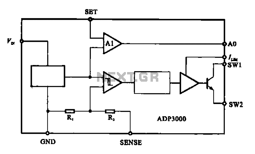
The ADP3000 is an integrated circuit featuring a block diagram that illustrates its internal structure as a high-frequency switching regulator. The ADP3000 integrated circuit is designed to provide efficient power management in various applications, particularly in systems requiring high-frequency switching...
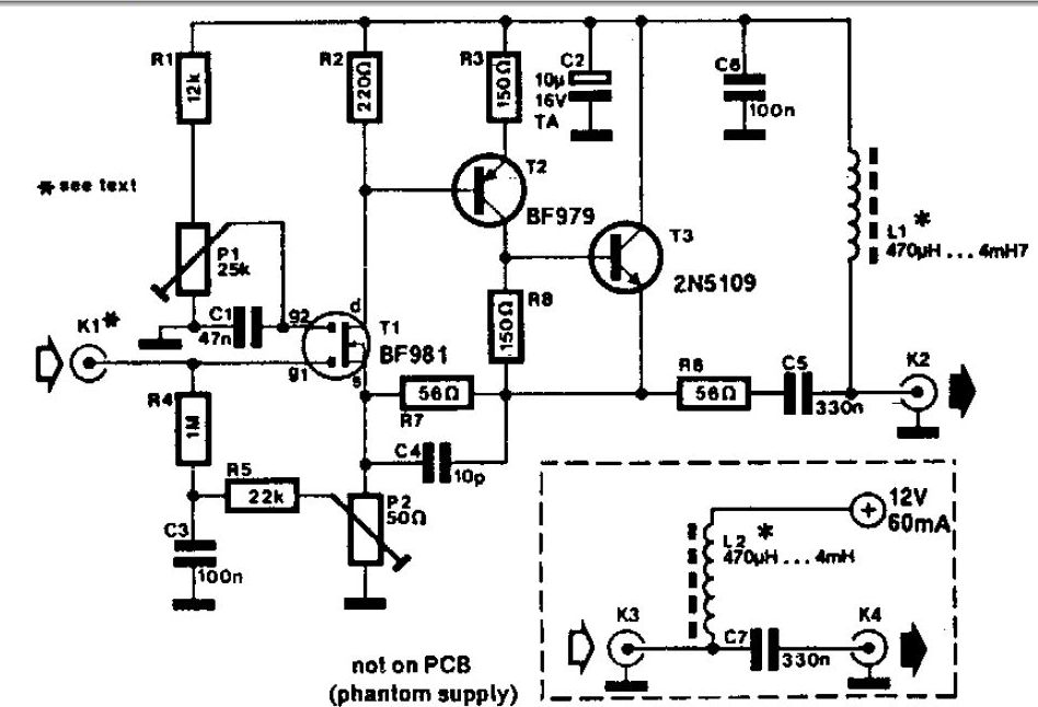
A whip antenna measuring between 30 to 50 cm is capable of receiving signals from 10 MHz to over 220 MHz. The circuit incorporates a BF981 dual-gate MOSFET (T1), which offers low noise characteristics, high input impedance, and enhanced performance. The...
Warning: include(partials/cookie-banner.php): Failed to open stream: Permission denied in /var/www/html/nextgr/view-circuit.php on line 713
Warning: include(): Failed opening 'partials/cookie-banner.php' for inclusion (include_path='.:/usr/share/php') in /var/www/html/nextgr/view-circuit.php on line 713