
Light Sensor Circuit
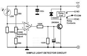
An ambient light sensor circuit typically consists of a light-dependent resistor (LDR) or phototransistor that detects the intensity of ambient light. The sensor converts the light intensity into a corresponding electrical signal, which can then be processed by other components in the circuit.
The primary components of this circuit include the light sensor (LDR or phototransistor), a resistor, and an operational amplifier (op-amp) or microcontroller for signal processing. The LDR exhibits a decrease in resistance with an increase in light intensity, allowing it to function effectively in varying lighting conditions. When light falls on the LDR, the resistance decreases, causing an increase in voltage across it, which can be measured and interpreted.
In typical applications, the output from the ambient light sensor can be used to control devices such as automatic lighting systems, where the lights are turned on or off based on the surrounding light levels. This can enhance energy efficiency by ensuring that lights are only active when necessary. Additionally, the circuit can be integrated into smart home systems, allowing for automated adjustments to lighting based on the time of day or occupancy.
For optimal performance, the circuit may include a calibration mechanism to adjust sensitivity levels, ensuring accurate readings in different environments. Furthermore, the use of filtering capacitors can stabilize the output signal and reduce noise, which is particularly important in environments with fluctuating light conditions.
Overall, the ambient light sensor circuit is a versatile and essential component in modern electronic systems, contributing to energy conservation and automation in various applications.Ambient Light Sensor Circuit Light sensor circuit, such as the name is a circuit that utilizes the light intensity / beam for the other applications do. 🔗 External reference
Related Circuits
The circuit consists of two synchronized multivibrators formed by a pair of 555 timer circuits. It is capable of generating two synchronized pulse signals, with the spacing and frequency adjustable by modifying the time constant. The circuit offers flexibility...
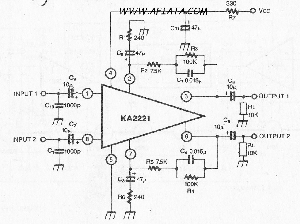
Audio amplifier circuit board with a dual low noise equalizer amplifier. The KA2221 is a monolithic integrated circuit that features 2-channel low noise amplifiers and a regulated power supply designed for car stereos. Key features include suitability for car...
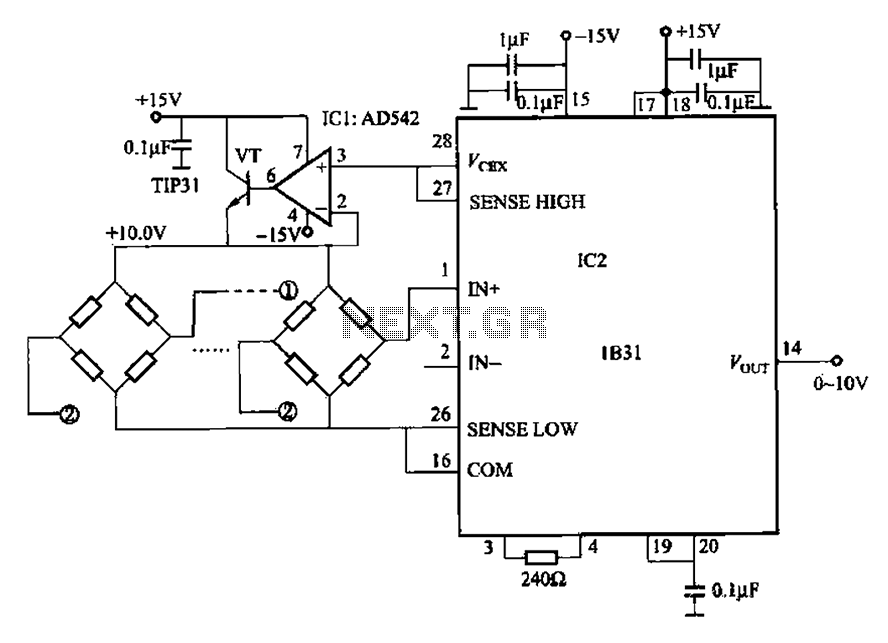
The 1832 low drift input has a temperature coefficient of 0.07 µV/°C (RTI, G 500) and exhibits excellent linearity with a maximum deviation of 0.005%. It can drive resistive loads greater than 120 ohms in a bridge excitation circuit,...
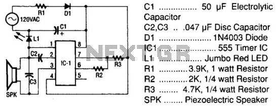
The tester comprises a rectifier circuit and a multivibrator circuit. The alternating current (AC) voltage is half-wave rectified by diode D1 and stored in capacitor C1. Resistor R1 is employed to limit the current through D1 to a safe...
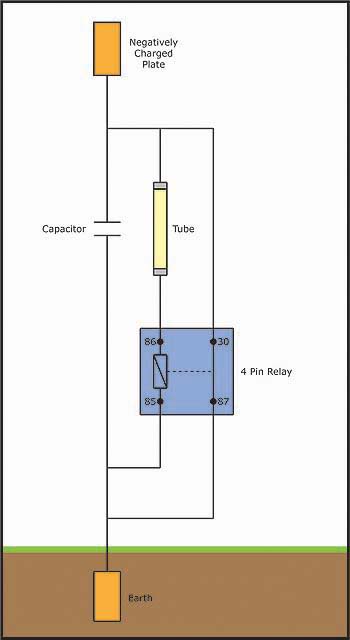
An individual has been studying Nikola Tesla's work for approximately 11 months and recently discovered Imhotep's concept of Radiant energy. The study of Nikola Tesla's contributions to electrical engineering and energy transmission has led to significant advancements in understanding electromagnetic...
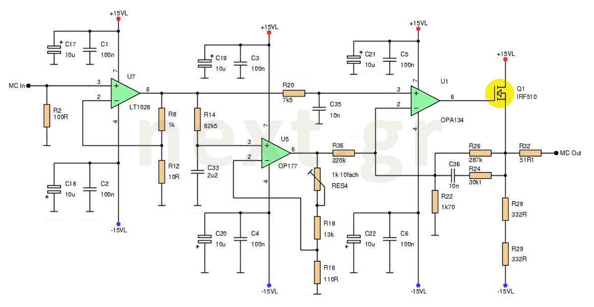
This microphone preamplifier circuit enhances the acoustic signal of a moving coil microphone (MC) with a sensitivity of 150μV at line level. In this design, a specific technique is not employed because the noise produced does not significantly impact...
Warning: include(partials/cookie-banner.php): Failed to open stream: Permission denied in /var/www/html/nextgr/view-circuit.php on line 713
Warning: include(): Failed opening 'partials/cookie-banner.php' for inclusion (include_path='.:/usr/share/php') in /var/www/html/nextgr/view-circuit.php on line 713