
Unity gain buffer circuit diagram of the MAX4102 4103
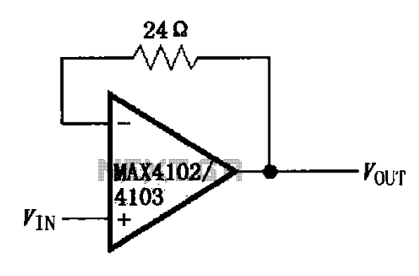
The MAX4102 and MAX4103 are high-speed operational amplifiers designed for unity gain applications. The circuit configuration employs a feedback loop that stabilizes the gain at one, allowing the output to closely follow the input voltage. The inclusion of a small resistor, typically around 24 ohms, in the feedback loop enhances the stability of the amplifier by providing a controlled path for feedback, which helps in minimizing distortion and improving the linearity of the output signal.
This unity gain buffer configuration is particularly advantageous in applications where high input impedance and low output impedance are required. The high input impedance prevents loading effects on the preceding circuit stage, while the low output impedance allows for effective driving of subsequent stages without significant voltage drop.
The design also ensures a wide bandwidth, which is crucial for high-frequency applications. The low overshoot characteristic indicates that the circuit can respond quickly to changes in input without generating excessive transient spikes, which is essential for maintaining signal integrity in fast-switching environments. The fast settling time further contributes to the circuit's performance, allowing it to quickly stabilize after a change in the input signal.
In summary, the MAX4102/4103 unity gain buffer circuit, characterized by its feedback resistor and operational amplifier configuration, is an effective solution for applications requiring high-speed signal processing with minimal distortion and excellent transient response. As shown by MAX4102/4103 unity gain buffer circuit shown in FIG. This circuit uses a small resistor (24 ) placed in the feedback loop amplifier constituting a unity gain buffer , so the maximum bandwidth of the circuit, and has a low overshoot and fast settling time.
Related Circuits
The audio from each radio will be connected to the iPod audio output and vice versa. This setup alters the impedance and can affect sound levels, potentially damaging the audio circuits of one or more radios involved. It is...
When the circuit is connected to hi-fi equipment or at both ends of the electronic instrument's speaker, the audio level can be modulated to a 500W lamp proportionally. This is achieved using three appropriate sets of audio filters and...

This design outlines a fire alarm circuit that utilizes a light-dependent resistor (LDR) and a lamp to detect fire. The alarm is activated by sensing the smoke produced during a fire. When smoke is present, it obstructs light from...
The 8-pin 555 timer is one of the most versatile integrated circuits (ICs) available, utilized in numerous projects. With minimal external components, it can be employed to construct various circuits, many of which do not pertain to timing applications....
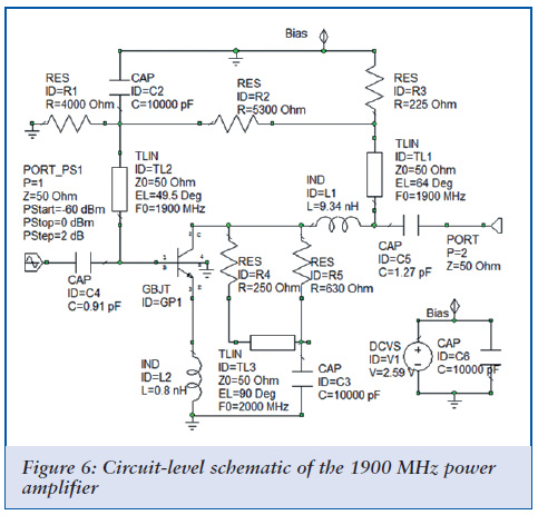
Achieving optimal performance from circuits used in third- and fourth-generation wireless systems necessitates tighter integration of previously separate tools. A degree of software synergy is crucial when designing circuits for modern wireless systems that utilize advanced modulation techniques alongside...
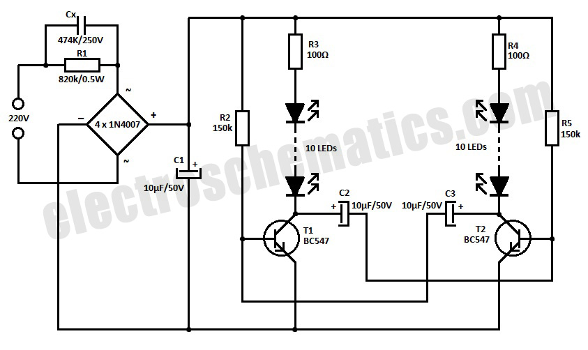
This is a simple LED blinker or flasher designed for decorative purposes. The circuit features 20 high-brightness LEDs that flash alternately, creating a vibrant color display. The LED blinker circuit typically consists of several key components including a microcontroller or...