
Feeding CB and Ham radio audio into the aux circuit
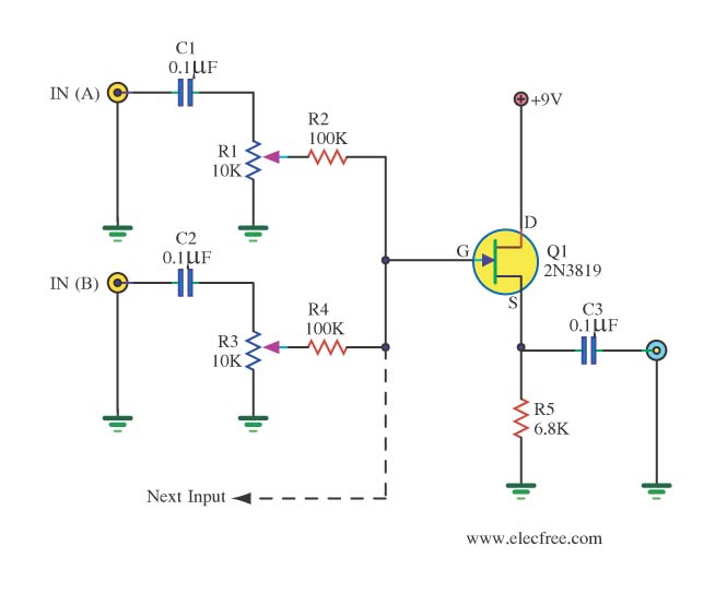
To create a functional audio mixer that connects two radio outputs to a single speaker, it is essential to address impedance matching and signal isolation to prevent damage to the audio circuits. The proposed design will incorporate capacitors at each output to ensure that the audio signals remain isolated, effectively blocking DC components while allowing AC audio signals to pass. This method will prevent interaction between the outputs, which could lead to distortion or damage.
Additionally, the use of blocking diodes can provide further protection by ensuring that signals do not back-feed into the radiating devices. Each radio output will be connected through a capacitor to the input of a summing amplifier, which will combine the audio signals. The summing amplifier can be configured using operational amplifiers (op-amps) to maintain a low output impedance, allowing for effective driving of the connected speaker.
To enhance the design, a volume control mechanism may be integrated, allowing for independent adjustment of each radio's contribution to the final audio output. This could be achieved using potentiometers placed before the summing amplifier inputs. Furthermore, if desired, a low-pass filter can be included to reduce high-frequency noise, ensuring a cleaner audio output.
The final schematic will consist of two input channels, each with a capacitor, followed by a summing amplifier stage, and a single output channel leading to the speaker. This design will ensure that the audio signals from the radios are mixed effectively while maintaining the integrity of each signal and protecting the audio circuits from potential damage.You`ll feed the audio from each radio into the ipod audio output, and vice versa. which changes the impedance and affects the sound levels (along with possibly damaging the audio circuit of one or all of the radios involved). I`m no expert, by I don`t think the resistors will do the job. You need to isolate each audio output from each other - just like the way the factory audio requires you to switch inputs to prevent more than
one audio output being fed into the system together at any time. You could do that with a capacitor on each output. We use blocking diodes in the aircraft that I work on, but I wont speak on that until I breadboard one up and give it a try. There are many audio systems that mix two audio outputs to an amp. Mic mixers, DJ systems, etc. I don`t want to dig into this that deep, but I honestly think I can build a mixer that will mix to radio outputs to one speaker, and do that without it costing too much.
Not exactly - you`ll feed the audio from each radio into the ipod audio output, and vice versa. which changes the impedance and affects the sound levels (along with possibly damaging the audio circuit of one or all of the radios involved). I`m no expert, by I don`t think the resistors will do the job. You need to isolate each audio output from each other - just like the way the factory audio requires you to switch inputs to prevent more than one audio output being fed into the system together at any time.
🔗 External reference
Related Circuits
A popular project among microcontroller enthusiasts is to build a radio-controlled clock. Tiny receiver boards are available, equipped with a pre-tuned ferrite antenna that receives and demodulates the DCF77 time signal broadcast from Mainflingen in Germany. DCF77 has an...
For several years, a rear fog lamp has been mandatory for trailers and caravans to enhance visibility in foggy conditions. When the fog lamp is activated, the fog lamp of the towing vehicle must be turned off to prevent...
The ZN414 is an economical, single-chip AM radio integrated circuit introduced in 1972 by Ferranti. The TDA7000 is a monolithic integrated circuit designed for mono FM portable radios or receivers, focusing on minimizing size. Additionally, there is an FM...
Xenon lamp, strobe light circuits, xenon strobe, photo flash, photoflash, schematics or diagrams, all free to use. The inspiration originated from a strobe circuit that was part of a school fire alarm. Xenon lamps are high-intensity discharge lamps that emit...
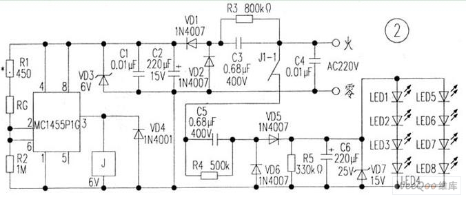
The circuit is depicted in Figure 1, while the electrical schematic diagram is presented in Figure 2. The AC voltage of 220V is reduced by components C3 and R3. The diodes VD1 and VD2 rectify the voltage, and capacitors...
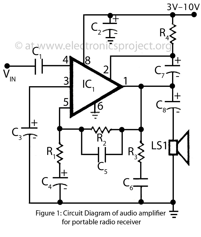
This is a simple audio amplifier circuit built around the BEL1895 1W audio amplifier integrated circuit (IC). This circuit serves as an alternative to more complex audio amplifier circuits designed for portable radio receivers. It does not require a...
Warning: include(partials/cookie-banner.php): Failed to open stream: Permission denied in /var/www/html/nextgr/view-circuit.php on line 713
Warning: include(): Failed opening 'partials/cookie-banner.php' for inclusion (include_path='.:/usr/share/php') in /var/www/html/nextgr/view-circuit.php on line 713