
DC motor armature resistance in series to start debugging circuit 2
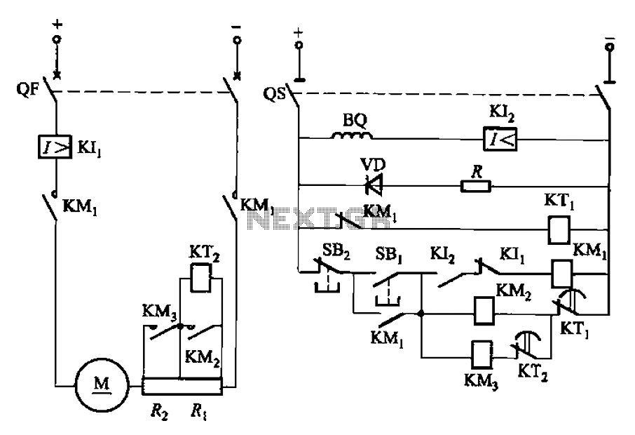
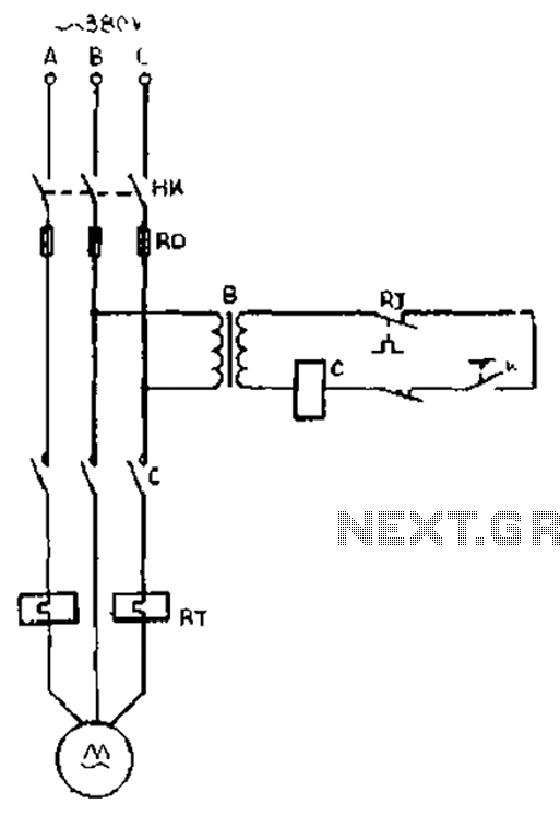
The described circuit operates a DC motor with a two-stage startup mechanism to manage inrush current and ensure smooth operation. The resistors Ri and Rz are strategically placed in series with the motor's armature to limit the initial current when the motor is powered on. This is essential for preventing damage to the motor and associated components due to high starting currents.
The control of the motor is facilitated by push-button switches, which allow the user to initiate or halt the motor's operation. When the start button is pressed, it energizes the relays KTi and KTz, which subsequently engage the startup resistors. This configuration allows the motor to ramp up to its operational speed gradually, reducing mechanical stress and electrical strain.
Once the motor reaches a certain speed, the relays automatically disengage the startup resistors, allowing the motor to operate at full efficiency. This automatic cut-in feature is crucial for optimizing performance and extending the lifespan of the motor. The use of relays in this circuit not only provides a reliable means of control but also allows for the incorporation of additional safety features, such as overload protection, depending on the specific application requirements.
Overall, the design of this DC motor control circuit exemplifies a practical approach to managing motor startup conditions, ensuring both operational efficiency and component protection. Circuit shown in Figure 3-191. The line in the DC motor armature circuit in series two-stage startup resistor Ri, Rz, Lee realized using the buttons to start and stop the motor control. During startup time by two relays KTi, KTz automatic cut in addition to two start-up resistor.
Related Circuits
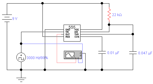
The standard assumption is that the phase shift sections operate independently. According to the equation provided, the loop phase shift reaches -180 degrees when the phase shift of each section is 60 degrees. This condition is met when ω...
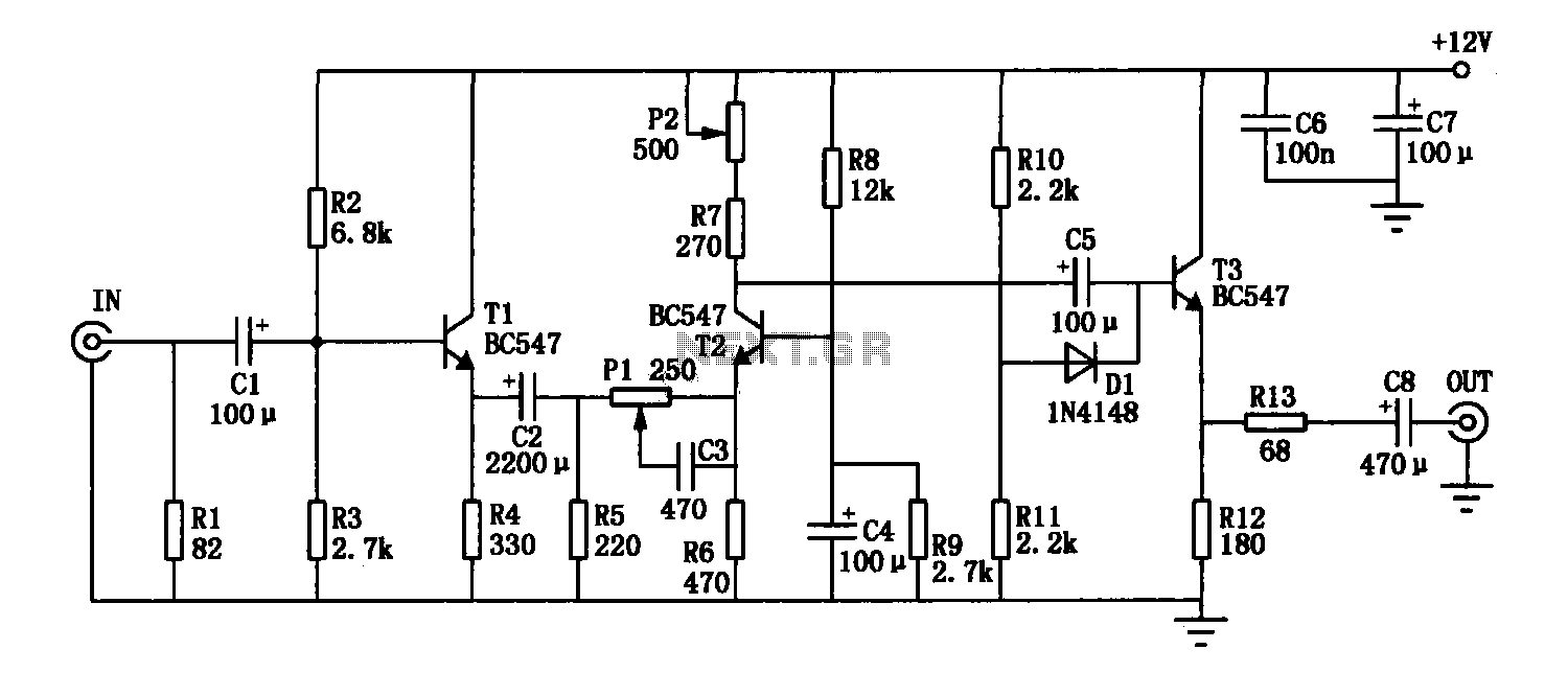
This simple circuit combines two or more audio channels into a single channel (for example, converting stereo to mono). The circuit is capable of mixing any number of channels and operates with minimal power consumption. While the schematic illustrates...
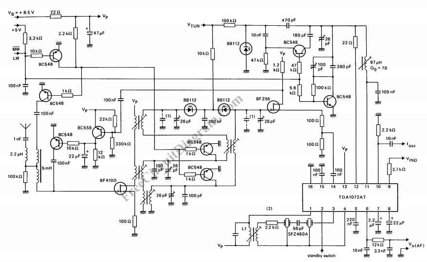
The TDA1072AT is a specialized integrated circuit designed for AM radio receivers, produced by Philips Semiconductors. This IC is intended for use in both mains-fed home receivers and car radios. It features a voltage-controlled oscillator that delivers signals with...
A DC motor reversing circuit using non-latching push button switches. Relays control forward, stop, and reverse action, and the motor cannot be switched from forward to reverse unless the stop switch is pressed first. The described circuit employs a system...
The enhancement circuit, as depicted, increases the high-frequency components of the video signal, thereby improving the contrast of the television image. It can be connected between the VCR and the TV SCART input. The circuit utilizes transistor T1 for...
The gear lathe is unloaded from the stop line as depicted in the figure. When the turning clutch is in the stop position, the limit switch XWK is disengaged, which immediately powers the AC contactor coil C to stop...
Warning: include(partials/cookie-banner.php): Failed to open stream: Permission denied in /var/www/html/nextgr/view-circuit.php on line 713
Warning: include(): Failed opening 'partials/cookie-banner.php' for inclusion (include_path='.:/usr/share/php') in /var/www/html/nextgr/view-circuit.php on line 713