
AM Radio Receiver Circuit Using TDA 1072AT IC

The TDA1072AT integrated circuit is a highly efficient solution for AM radio applications, incorporating advanced features to enhance performance. The voltage-controlled oscillator (VCO) within the TDA1072AT is crucial for maintaining high fidelity in the received audio signal. Its ability to provide low distortion across a wide frequency range ensures that the audio output remains clear and consistent, which is particularly important for radio broadcasts that may vary in signal quality.
The circuit design of the TDA1072AT emphasizes symmetry, which is a key factor in minimizing unwanted RF radiation and improving overall sensitivity to interference. This symmetrical layout allows for better performance in diverse environments, making it suitable for both stationary and mobile applications. The integration of variable capacitance diodes for tuning further enhances the versatility of the receiver, enabling precise frequency adjustments without compromising signal integrity.
In practical applications, the output signal from pin 9 can be connected to a signal strength meter, providing real-time feedback on the quality of the received signal. This feature is invaluable for users who need to optimize their radio setup, as it allows for adjustments to be made based on actual signal performance.
The accompanying schematic diagram illustrates the typical configuration of the AM radio receiver circuit utilizing the TDA1072AT. Key components in the circuit may include tuning capacitors, inductors, and additional passive elements that work in concert with the IC to achieve optimal performance. By following the schematic, engineers and hobbyists can replicate the design, ensuring that their AM radio receivers operate effectively within the specified parameters.
Overall, the TDA1072AT represents a robust solution for AM radio applications, combining advanced technology with practical features that cater to both consumer and professional needs in the realm of radio reception.TDA1072AT is a special purpose integrated circuit for AM radio receiver from Philips Semiconductors. The integrated circuit is designed for mains-fed home receivers and car radios. The voltage-controlled oscillator provides signals with extremely low distortion and high spectral purity over the whole frequency range even when tuning with variable capacitance diodes. RF radiation and sensitivity to interference are minimized by an almost symmetrical design. Here is the schematic diagram of this AM radio receiver circuit: The signal coming out from pin 9 of the TDA1072AT IC can be used to drive a meter to indicate the signal strength. [Circuit`s schematic diagram source: Philips Semiconductor Application Notes] 🔗 External reference
Related Circuits
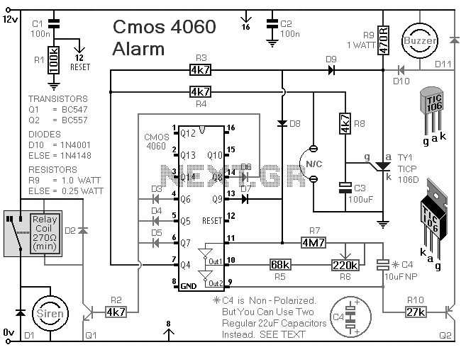
This is a single-zone alarm system equipped with automatic exit, entry, and siren cut-off timers. It can accommodate various types of normally-closed input devices, such as magnetic reed contacts, foil tape, and passive infrared sensors (PIRs). Additionally, it is...
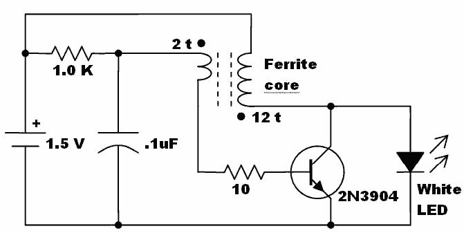
Here is an idea for a voltage booster that enables the lighting of a white LED using a single AA cell. This presents an opportunity to utilize one of the ferrite cores and white LED holiday lights mentioned in...
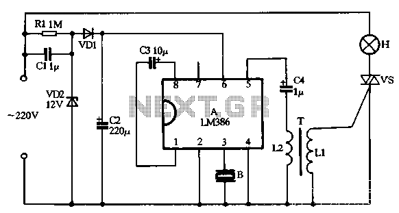
VD1, VD2, C1, and C2 comprise a simple half-wave rectifier capacitor step-down voltage regulator circuit, providing an output of approximately 12V for a linear power supply connected to the LM386. The LM386 is linked to the inverting input terminal...
The schematic diagram presented below illustrates a simple FM receiver constructed using four transistors. The signal from the antenna passes through the trimmer capacitor C1 before reaching the input of the first stage, which operates as a super-regenerative detector...

This sensor switch circuit features nine channels and consists of three integrated circuits along with several resistors. The 74HC147, which has a high input impedance, enables the use of 4.7 MΩ resistors to establish a logic level "high" for...
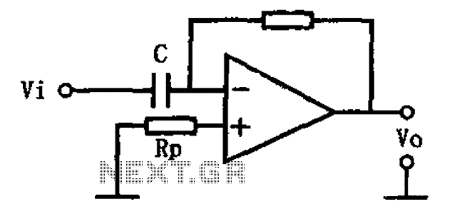
This circuit illustrates a basic differentiating circuit. The differential operation circuit can process input and output signals, establishing a relationship between the output and the input. A basic differentiating circuit is designed to produce an output that is proportional to...