
Separately excited DC motor reversing circuit
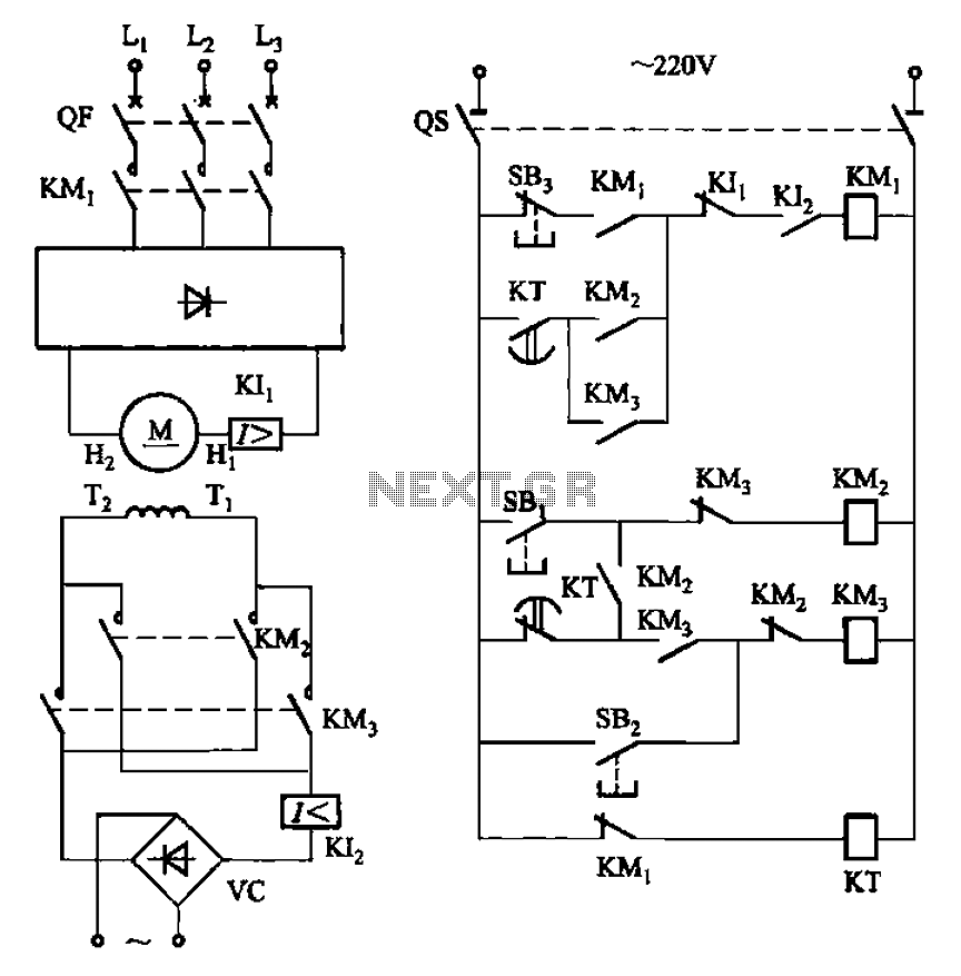
The schematic involves a separately excited DC motor, which is powered by an external voltage source that is independent of the armature circuit. This configuration allows for better control over the motor speed and torque.
In the circuit, a relay is employed to manage the motor's operation. The delay action relay is crucial for controlling the timing of the motor's reversal. When the motor is commanded to stop, the relay introduces a predefined delay before reversing the motor's direction. This delay is necessary to allow the motor to come to a complete stop before engaging the opposite polarity, thereby preventing mechanical stress and potential damage.
The braking mechanism is passive in this circuit, meaning that it does not actively apply a braking force but relies on the natural inertia of the motor and the load it drives. This approach can be beneficial in applications where rapid deceleration is not critical, but it requires careful timing to ensure smooth transitions between forward and reverse operations.
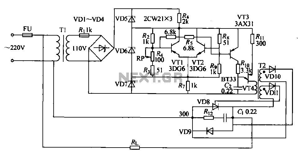
Overall, the circuit design emphasizes the importance of timing and control in motor applications, particularly in scenarios where alternating direction is required. The use of a separately excited motor combined with a delay action relay provides a reliable method for achieving controlled reversals. Circuit shown in Figure 3-193. Motor is separately excited DC motor. The brake circuit does not take measures, so the positive reversals alternately using delay action time rel ay KT ensure after stopping to reverse the motor started.
Related Circuits
This project is used as an electronic private exchange. It has two telephones, which have the intercom facility, and they can be connected to the telephone line. All the functions are controlled by the 8-bit microcontroller AT89C2051 which has...
The circuit diagram features two LT1398 operational amplifiers from Linear Technology, which are utilized to generate buffered color-difference signals from RGB (red-green-blue) inputs. The red (R) input is received through a 75-ohm coaxial cable and is directed to the...
The circuit described is a simple intercom system that utilizes a single LM386 integrated circuit, a 2N3904 transistor, and several additional components. The LM386 is a widely recognized amplifier IC commonly employed by electronics enthusiasts in audio applications. In...
The circuit consists of two differential amplifier transistors configured with a voltage dividing type bias circuit, measuring the resistance of four arms in a bridge configuration. The product includes a platinum resistance sensor, which exhibits an increase in resistance...
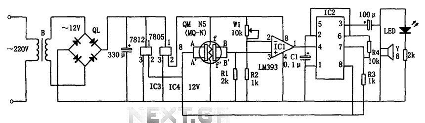
The circuit consists of a buck rectifier and voltage regulator, a gas sensor, a comparator circuit, and an alarm sound circuit. The buck regulator circuit includes a transformer, a bridge rectifier, and components such as QL, IC3 (7812), and...
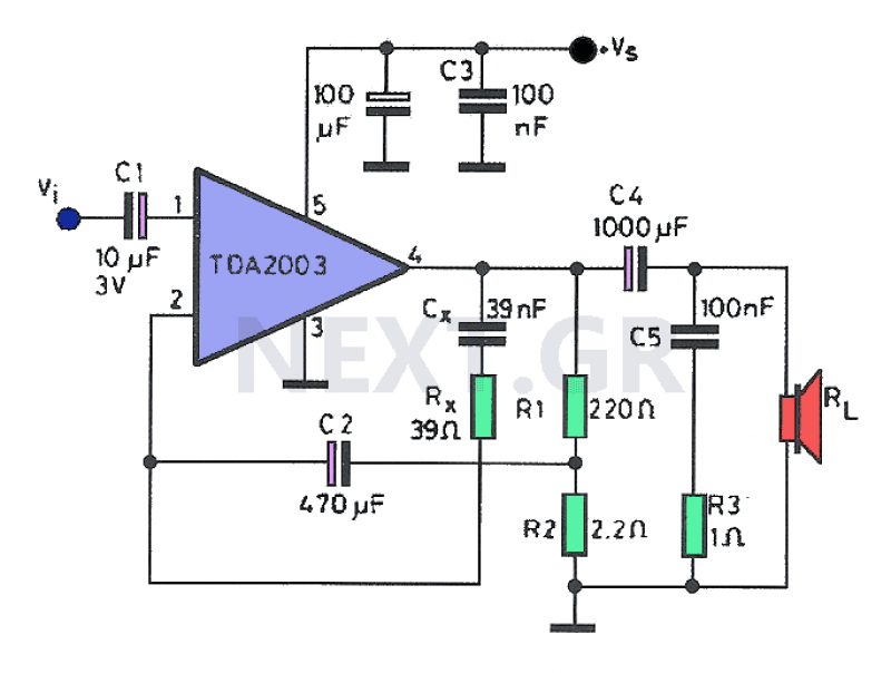
Often, a small amplifier is required to accommodate the needs of compact spaces. This amplifier can be configured as either mono or stereo, and its circuitry is capable of efficiently driving two small speakers. Constructing the amplifier necessitates only...