
SCR furnace temperature regulating circuit

The described circuit utilizes a differential amplifier configuration to monitor and regulate the temperature of an electric furnace. The two transistors in the differential amplifier are biased through a voltage divider arrangement, ensuring stable operation across varying temperatures. The platinum resistance sensor serves as the primary temperature sensing element, characterized by its predictable resistance change in response to temperature fluctuations.
In the bridge circuit, the four arms are balanced under normal operating conditions, with the platinum sensor providing a variable resistance that alters the balance as temperature changes. The potentiometer RP allows for user-defined temperature settings, enabling precise control over the furnace's operating conditions.
As the furnace temperature deviates from the set point, the circuit responds dynamically. A decrease in the measured temperature leads to a reduction in R4, disrupting the balance of the bridge. This unbalance generates a differential voltage that affects the base-emitter junctions of the transistors. The resulting changes in collector currents through the emitter resistors lead to a cascading effect that ultimately adjusts the firing angle of the thyristor, thereby modulating the power delivered to the heating element.
The integration of the 3AX31B transistor within the charging circuit is crucial for enhancing the response time of the system. By controlling the charging current, the circuit ensures rapid adjustments to the thyristor's conduction angle, facilitating swift temperature increases when necessary. This feedback mechanism is essential for maintaining the desired operating temperature and preventing overheating.
Overall, the described electronic schematic provides a sophisticated solution for automatic temperature control in electric furnaces, leveraging the properties of differential amplifiers and the thermal characteristics of platinum resistance sensors.Consisting of two differential amplifier transistors voltage dividing type bias circuit, and this resistance is measured four bridge four of arm. Wherein the product is a plati num resistance, its resistance increases with increasing temperature, and decreases with decreasing temperature, it is to release electric furnace temperature measurement devices. Change the resistance of the potentiometer RP can be given a furnace. When compared with a given oven temperature is low. R4 resistance decreases, the bridge out of balance. VT2 group Xi potential drop, the collector current decreases. As the two tube collector current flows through the emitter resistor (lk), so that the emitter potential of the two tubes of decline, VT1 collector current increases, the collector potential drop in the charging circuit transistor 3AX31B base potential drop, the charging current increases, the trigger pulse in advance, the thyristor conduction angle increases, the furnace temperature rises.
When the temperature is high, everything changes on said opposite. Therefore, the differential amplifier can be used to achieve the purpose of automatically adjusting the furnace temperature.
Related Circuits
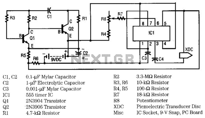
This circuit utilizes two transistors and one integrated circuit (555 timer IC) to generate a pulsating ultrasonic frequency. Transistors Q1 and Q2 are configured in a direct-coupled oscillator arrangement. The frequency of the oscillator is determined by capacitor C1....
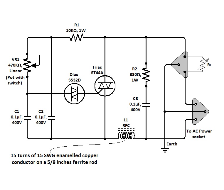
The circuit of a simple triac light dimmer can be used to dim incandescent lamps directly from AC mains. It is easy to construct and requires very few components. A potentiometer is utilized to control the load power or...
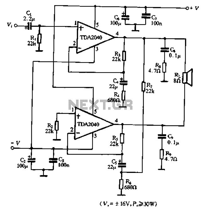
The TDA2040 is a power audio amplifier with a wider operating voltage range compared to the TDA2030, ranging from 4V to 20V. It can deliver an output power of 18W at a load of 4 ohms when supplied with...
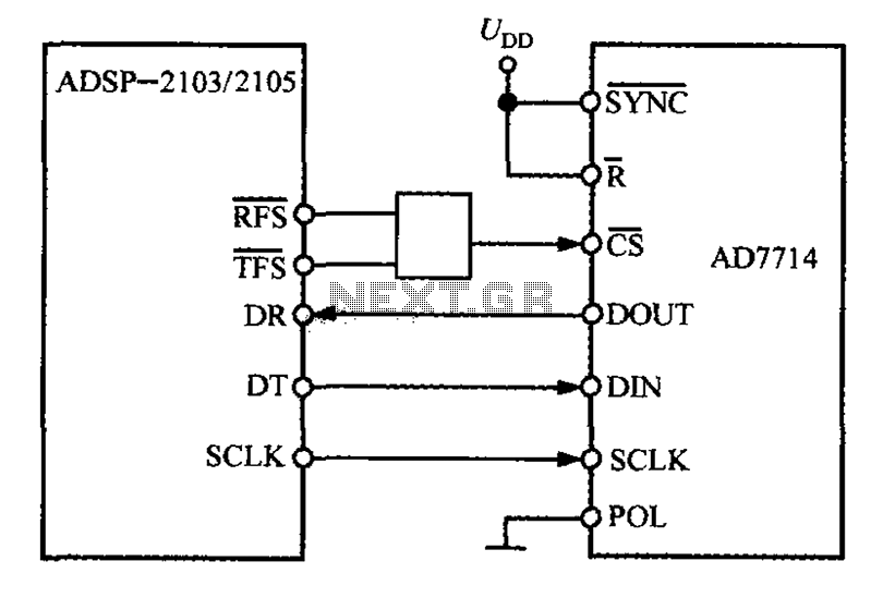
The ADSP-2103 and ADSP-2105 are digital signal processors that interface with the AD7714. When the output is active, the ADSP-2103/2105 configuration includes the RFS non-TES non-terminal set to a low level, while the SCLK terminal is configured for serial...
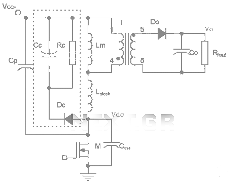
The work process analysis circuit diagram illustrates the use of a flyback converter transformer model. The flyback transformer primarily consists of ideal transformer magnetizing inductance and leakage inductance components. The flyback converter circuit exhibits high-frequency resonance at both ends...
This is a pressure sensor signal conditioning circuit. It is a simple and inexpensive circuit due to its small geometry and the use of a straightforward pressure sensor. The pressure sensor signal conditioning circuit is designed to convert the raw...