
It can send a signal to start forward rotation start circuit

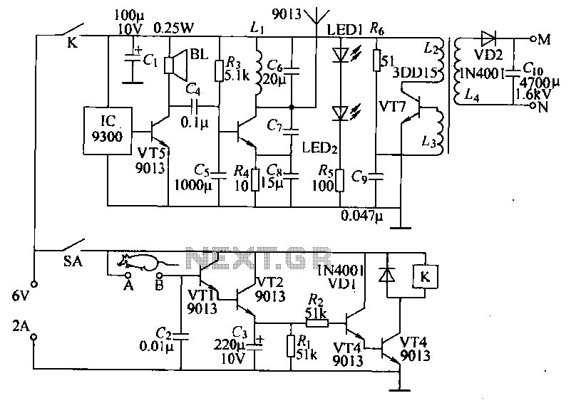
The circuit operates by integrating an audio output component, such as a piezo buzzer or speaker, which generates a distinct startup sound when the motor is activated. This auditory signal serves as an alert to operators that the motor is in the process of starting. Concurrently, a visual indicator, typically an LED, emits a light signal that remains illuminated until the motor has successfully reached its operational state. Once the motor is fully operational, the circuit is designed to deactivate both the sound and light signals, providing clear feedback to the user that the startup sequence has been completed.
To enhance safety, the circuit may include additional features such as overload protection, which prevents the motor from starting under excessive load conditions. This can be achieved through the use of current sensors that monitor the motor's input current. If an overload is detected, the circuit can be designed to interrupt the power supply to the motor, thereby preventing potential damage and ensuring safe operation.
Moreover, the circuit can be configured with a delay timer to allow for a gradual increase in motor speed, further minimizing mechanical stress and enhancing the longevity of the equipment. This functionality can be implemented using a microcontroller or a simple RC timing circuit, depending on the complexity required.
In summary, the circuit not only provides auditory and visual feedback during the motor startup process but also incorporates safety measures to protect the machinery and ensure reliable operation across a diverse range of applications. Circuit shown in Figure 3-21. It issued motor startup sound, light signal to start the process is completed, the signal stops. This circuit is adapted to drive the motor by mea ns of a large range of movement of machinery and equipment, to ensure safety.
Related Circuits
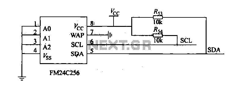
The FM24C256 is utilized as a slave interface circuit in an I2C bus configuration, with the address format specified in Table 27-3. The address pins A2, A1, and A0 are set to low; however, for extended storage capacity, adjustments...
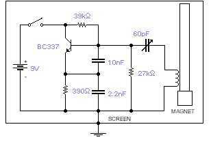
This basic oscillator will detect the Earth magnetic field. The ferrite rod and coil are taken from an old Medium Wave receiver and a small magnet is glued at one end. Tune to a medium wave commercial station until...
Power-saving electronic mousetrap. This example describes the minimal power consumption, which only occurs when a mouse enters the control zone during foraging activities. After a 30-second delay, the system enters a wait state, making it suitable for outdoor use....
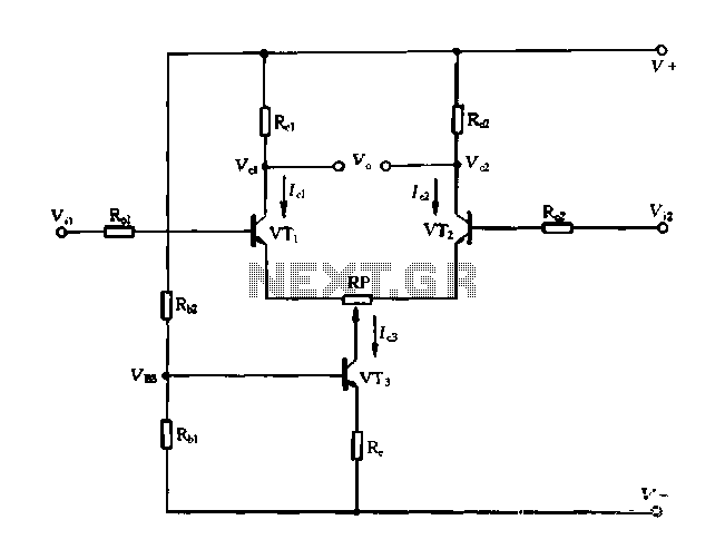
A differential amplifier with a constant current source is illustrated in Figure 1-27. As long as capacitor C3 is maintained at a constant value, capacitors C1 and C2 cannot be simultaneously increased or decreased, preventing voltage drift. The differential...
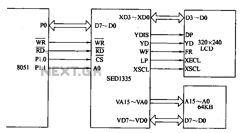
The MCS-51 series single-chip interface circuit 8051 is utilized to control the SED1335 35 dot matrix LCD display. This controller can manage up to a 640x256 dot matrix LCD display for both graphics and character representation, with the capability...

TDA2004 Car Battery 12W Stereo Amplifier Circuit. Its main features are low distortion, low noise, and high reliability of the chip. The TDA2004 is a highly integrated audio amplifier designed specifically for automotive applications. This circuit is capable of delivering...