
Bistable circuit control motor reversing circuit

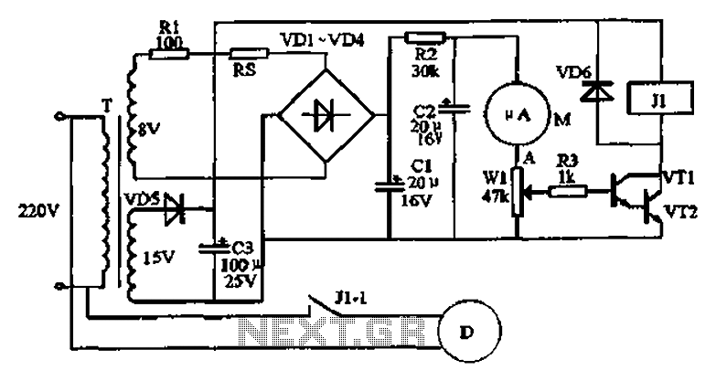
The schematic represents a bistable motor control circuit that is capable of reversing the direction of a motor while ensuring a safe transition between operational states. The circuit consists of a microcontroller or a relay-based control unit that manages the motor's direction based on inputs from the limit switches. The limit switches, sQi and SQ2, are critical components that detect the motor's position, allowing for precise control over its operation.
The time delay feature is achieved through the use of timing components, specifically resistors and capacitors (R1, R2, C1, C2). The values of these components can be adjusted to set the desired delay time, which is crucial for preventing mechanical stress on the motor during direction changes. The voltage regulator's specifications also play a significant role in ensuring that the circuit operates within optimal voltage levels, contributing to the reliability and longevity of the motor.
When the motor reaches a limit switch, the circuit responds by reversing the motor's direction after the specified delay. This functionality is essential in applications where the motor must operate in both forward and reverse directions without causing damage to the mechanical components. The design of the circuit allows for flexibility in adjusting the timing and operational parameters, making it suitable for various applications in automation and control systems. Circuit shown in Figure 3-72. The circuit uses deformable bistable reversing motor control circuit automatically run and stop there during the time delay (time adjustable), to protect the motor from impact when the motor reversing conversion. Figure, sQi and SQ2 are forward and reverse limit switch terminals. Adjustment R], R2, C, Cz values and choose different models, specifications of the regulator and Vsl vs, Can change the stop (delay) time.
Related Circuits
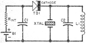
Leo Esaki invented the tunnel diode in 1957 while working at Sony (then known as Tokyo Tsushin Kogyo). Tunnel diodes feature a very narrow, heavily doped p-n junction approximately 10 nm wide, which exhibits a broken bandgap. This configuration...
When the power is connected to the circuit by turning on SW2, RELAY1 gets energized for the time it takes to load C3 through R1 and R3. After that, the relay gets de-energized, and C3 gets discharged through R2...
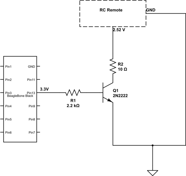
The remote control of an RC car was modified by extending wires from the backward, forward, left, and right switches. Grounding any of these wires completes the circuit and sends a signal to the car. The intention is to...
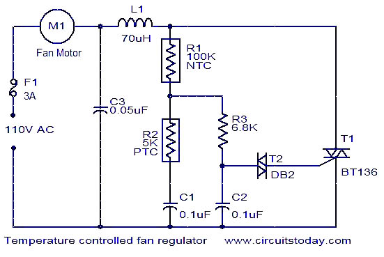
The function is designed to automatically control the speed of a fan based on the temperature. Components include a BT136 Triac, capacitor, resistor, relay, and fan motor. The circuit employs a temperature sensing mechanism to monitor ambient temperature levels. A...
A functional circuit utilizing an operational amplifier (op-amp); however, the instructor indicated that op-amps can be challenging to work with and provided transistors as an alternative. Operational amplifiers (op-amps) are versatile components commonly used in various electronic circuits for...
An automatic humidifier can be utilized for humidity control in households, hatcheries, poultry farms, or juvenile poultry houses. When the humidity level falls below 50%, the automatic humidifier activates to maintain a specific humidity level that is beneficial for...