
BT136 Temperature Controlled Fan Regulator

The circuit employs a temperature sensing mechanism to monitor ambient temperature levels. A thermistor or similar temperature sensor can be integrated into the circuit to provide real-time temperature readings. This sensor outputs a voltage that varies with temperature, which is then processed by a microcontroller or comparator circuit.
The BT136 Triac is utilized as the primary switching device to control the power delivered to the fan motor. When the temperature exceeds a predefined threshold, the microcontroller activates the Triac, allowing current to flow to the fan motor. The speed of the fan can be modulated by adjusting the phase angle of the AC waveform using a zero-cross detection circuit, which helps in controlling the firing angle of the Triac.
Capacitors and resistors are used in the circuit to filter noise and stabilize voltage levels, ensuring reliable operation. A relay may be included for isolation and to handle higher current loads, providing additional safety and control over the fan motor's operation.
The overall design ensures efficient fan speed regulation, allowing for energy savings and improved comfort in environments where temperature control is critical. This automated system enhances user convenience by eliminating the need for manual adjustments while maintaining optimal airflow based on temperature conditions.The function for automatically control the speed of your fan according to the temperature. Component: BT136 Triac, Capacitor, Resistor, Relay, Fan Motor, .. 🔗 External reference
Related Circuits
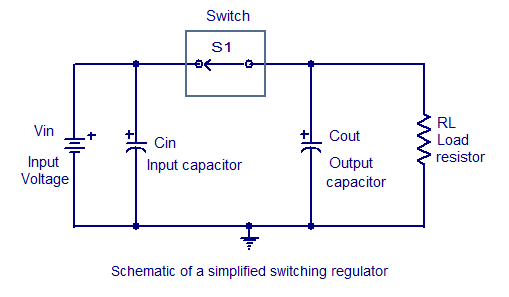
Switching regulators operate by drawing small amounts of energy from the input source and transferring it incrementally to the output. This is achieved using an electronic switch, which functions at a predetermined frequency, acting as a gate between the...
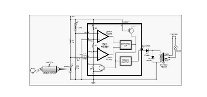
This circuit is designed around a 555 timer and utilizes a minimal number of components. Due to its simplicity, it can be easily constructed and operated by beginners. The circuit leverages the 555 timer IC, which is a versatile and...
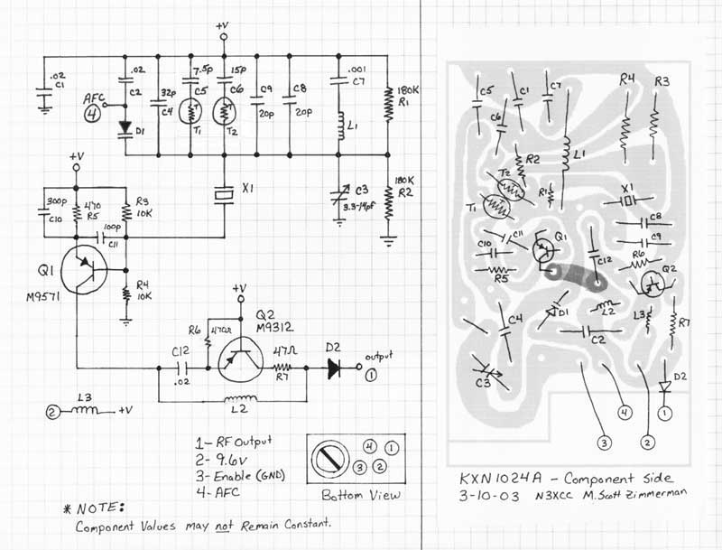
This document addresses the replacement of the crystal in various types of Temperature Compensated Crystal Oscillators (TCXOs), including Motorola "Channel Elements," GE "Integrated Circuit Oscillator Modules" (often referred to as ICOMs), and RCA TCXOs. The term "element" will be...
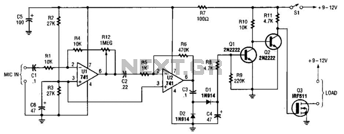
This audio-controlled switch integrates a pair of 741 operational amplifiers, two 2N2222 general-purpose transistors, an hcxFET, and several supporting components into a circuit capable of activating devices such as a tape recorder, a transmitter, or virtually any sound-activated equipment. The...
In a hybrid system, an analog system with digital control, voltage-controlled components are crucial as they can be interfaced with a Digital-to-Analog Converter (DAC) from the digital system. In hybrid systems, the integration of analog and digital components allows...
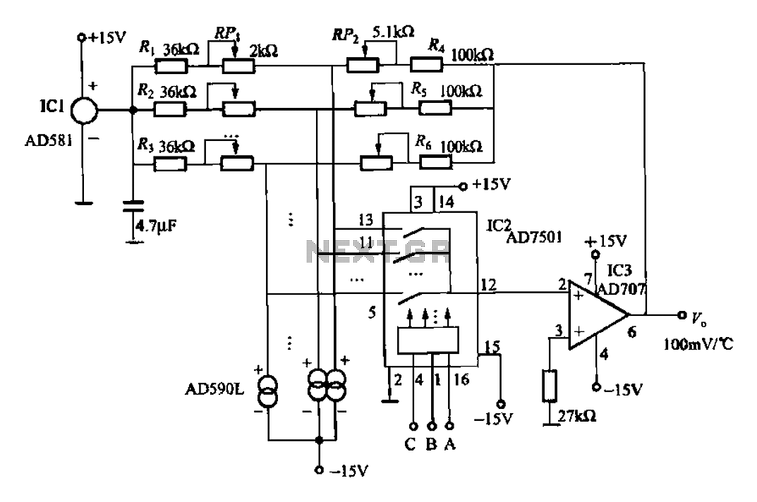
An 8-channel temperature detection circuit capable of monitoring eight different temperature sensors. The D581 serves as a 10.00V precision reference voltage source, providing a stable reference level for the detection circuit. Resistors RPi, RP2, and R4, along with the...