
555 practical DC stepless dimmer circuit diagram
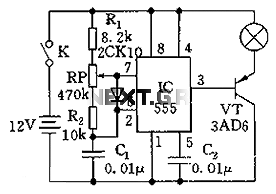
The circuit operates as an astable multivibrator, which continuously switches between high and low states, generating a square wave output. The 555 timer's configuration allows for rapid cycling, where the frequency of oscillation is determined by the values of the resistors and capacitor. The resistors R1 and R2 set the timing intervals, while RP serves as a variable resistor, enabling fine-tuning of the duty cycle.
When RP is adjusted, it alters the charge and discharge times of capacitor C1, directly impacting the output pulse width. A lower duty cycle corresponds to a shorter "on" time, resulting in reduced power supplied to the lamp, thereby dimming its brightness. Conversely, increasing the duty cycle allows more power to reach the lamp, brightening it.
The output from the 555 timer can be used to control a transistor or a triac, which acts as a switch for the lamp. This configuration allows for efficient control of AC or DC lamps, making it suitable for various lighting applications. The design's ability to provide a smooth transition between brightness levels enhances user experience, making it ideal for environments requiring adjustable lighting conditions.
Overall, this dimmer circuit is a practical application of the 555 timer in creating a flexible lighting solution, combining simplicity in design with effective performance in brightness control. Circuit shown in Figure dimmer to 555 as the core component. 555 and R1, RP, R2, C1 composition astable multivibrator, the oscillation frequency f 1.44/(R1 + RP + R2) C1, aroun d about 650Hz, the duty cycle can be varied by adjusting the RP, from change 4.5% to 95.5%, and thus the brightness of the lamp has a wide range of changes to achieve stepless dimming.
Related Circuits
The circuits in Figure 1 and Figure 2 demonstrate specific advantages over the circuit presented in the Design Idea in EDN, titled "Circuit detects first event," published on May 3, 2001, page 89. The n-player first-event detection circuit provides...
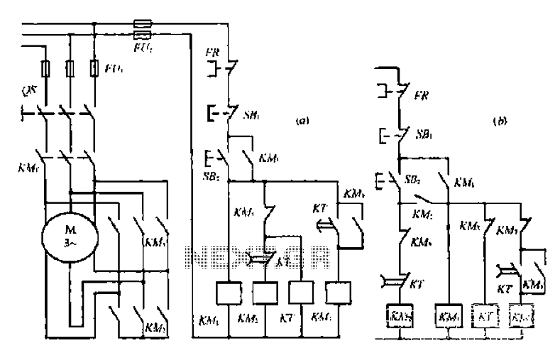
A star-delta switch is utilized for starting circuits, commonly depicted in Figure I-5 (a) of the knife wiring. While this method is effective, it poses security risks. When the motor starts, it can create significant voltage fluctuations that may...
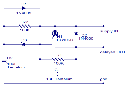
The circuit diagram presented is of a straightforward DC power delay circuit utilizing a silicon-controlled rectifier (SCR). This circuit is quite useful and can be applied in various scenarios. The operation of this circuit is uncomplicated. Upon the application...

This FM spy telephone circuit is connected in series with the phone line. When there is a signal on the wires, this transmitter will radiate airwaves through the wires. This FM spy telephone circuit operates by integrating with the existing...
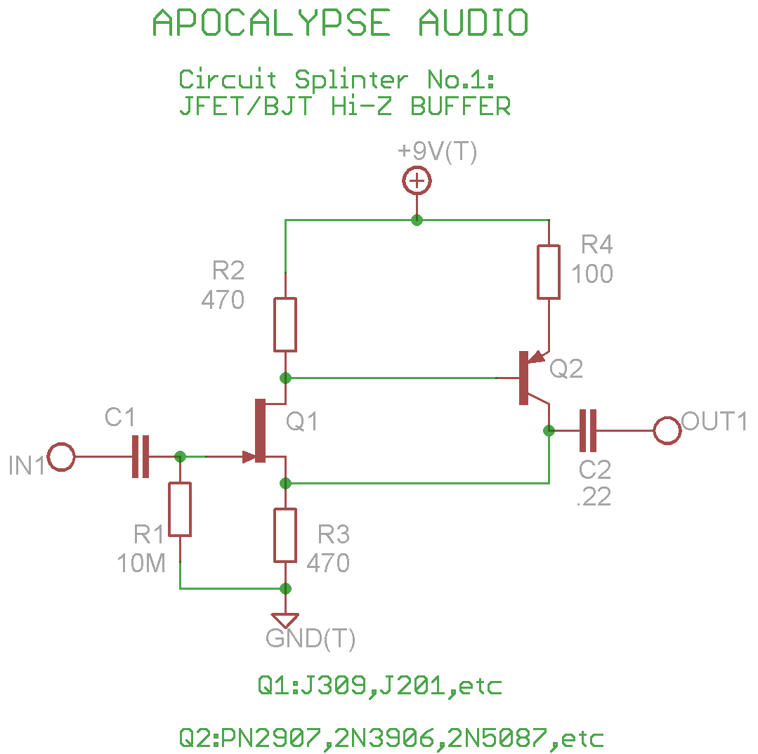
This is a common circuit often found in various resources, yet it appears to be less prevalent in stompbox applications. The circuit utilizes an NPN JFET DC coupled with a PNP BJT. The FET provides a significantly higher input...

This amplifier is designed with the following specifications: distortion less than 0.1% at full power of 100W even at 20KHz, with power attributed to an extended bandwidth. The output transistors are protected against short circuits, and the power supply...