
Spy Telephone Circuit
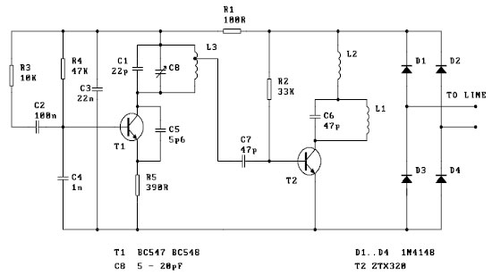
This FM spy telephone circuit operates by integrating with the existing phone line, allowing it to monitor and transmit audio signals. The circuit is designed to be installed in series, meaning it is placed in line with the telephone's wiring. This configuration enables the circuit to capture audio signals during phone calls.
The core component of the circuit is a frequency modulation (FM) transmitter, which converts the audio signals from the phone line into radio waves. These radio waves can then be picked up by a compatible receiver within a certain range. The circuit typically consists of several key elements: a microphone or audio input stage, modulation circuitry, an oscillator, and an antenna.
The audio input stage is responsible for capturing the sound from the phone line, which is then fed into the modulation circuitry. Here, the audio signal is used to modulate a carrier frequency generated by the oscillator. The modulation process encodes the audio information onto the carrier wave, allowing it to be transmitted wirelessly.
The antenna is crucial for radiating the modulated signals into the air. The design of the antenna must be appropriate for the frequency being used to ensure effective transmission. Additionally, power supply considerations are essential, as the circuit requires a stable voltage to operate efficiently.
Overall, this circuit is a sophisticated device that leverages existing telephone infrastructure to enable covert audio monitoring through FM transmission. Its design must adhere to relevant legal and ethical standards, as the use of such devices may be subject to regulations regarding privacy and surveillance.This FM spy telephone circuit is mounted serrial with the phone line. When is signal on the wires this transmitter will radiate airwaves thru the wires wic.. 🔗 External reference
Related Circuits
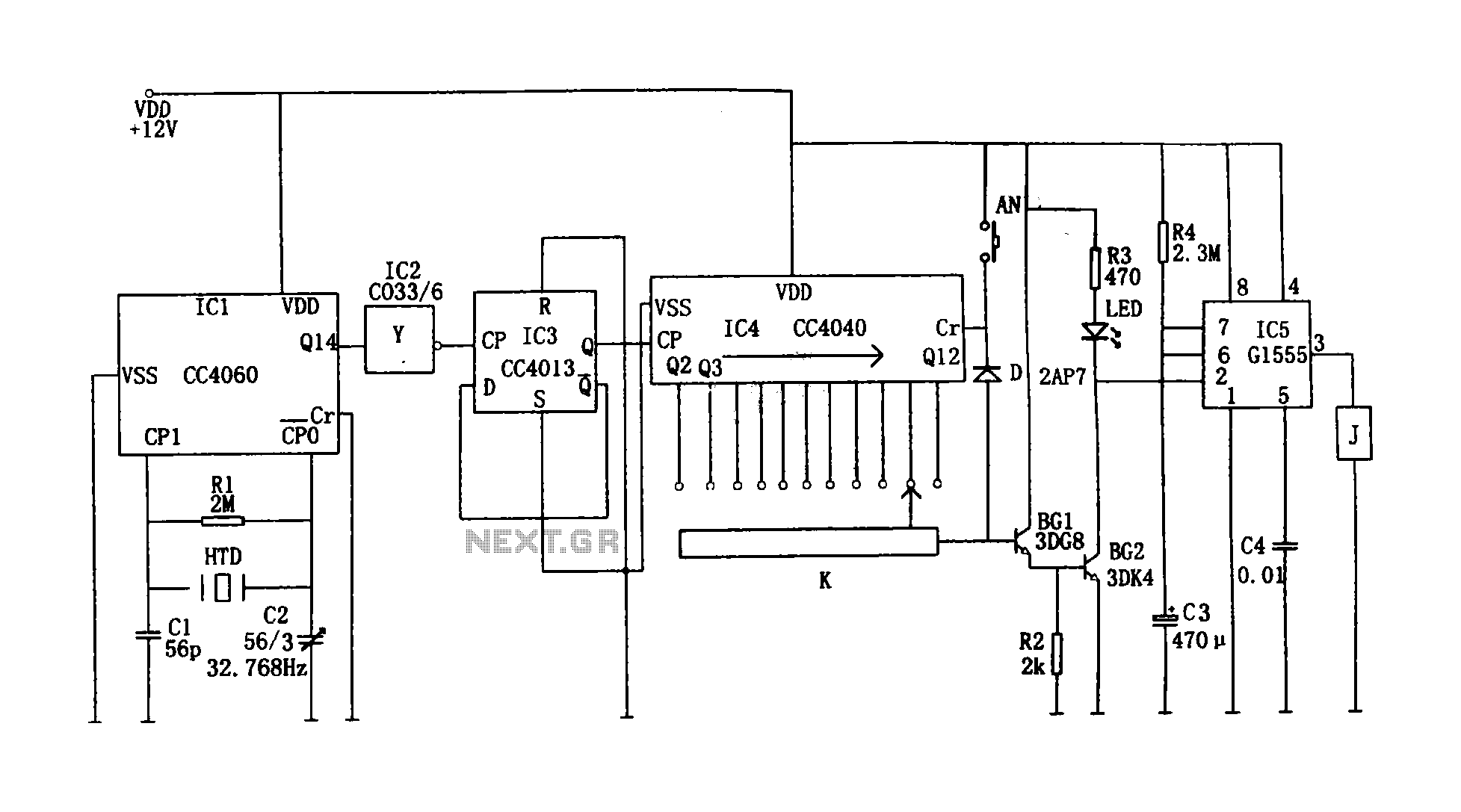
This circuit illustrates a precision digital timing control system. The controller includes a crystal oscillator circuit, a divider, a counting circuit, and monostable flip-flops. The crystal oscillator circuit features a series of 14 binary counters/dividers, a watch crystal operating...
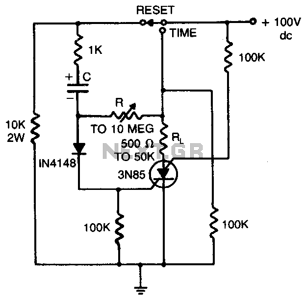
Load current starts approximately 0 RC after the switch is thrown. The statement indicates that the load current begins at approximately 0 ohms after a switch is activated. This scenario is common in electronic circuits where a switch controls the...
This is a 25 Watt basic power amplifier designed to be relatively easy to build at a reasonable cost. It offers better performance than the standard STK module amplifiers commonly used in nearly all mass-market stereo receivers manufactured today. The...
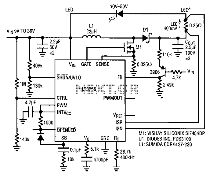
Common LED driver requirements include a wide and overlapping range of LED string voltages and input voltages. Many designers prefer to use an LED driver circuit that accommodates various battery power sources and multiple LED strings. This universal configuration...
The Link circuitry is simple and efficient, employing just two integrated circuits (ICs), a few transistors, and common components. It operates on 12 volts and is easy to assemble. This intercom system can connect various locations such as the...
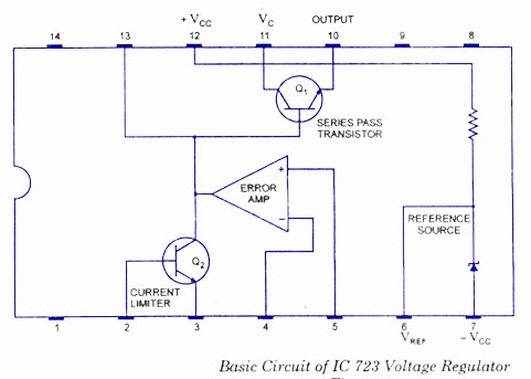
The working and block diagram of the IC 723 Voltage Regulator is provided along with the circuit diagram and applications. The IC 723 is a voltage regulator integrated circuit that is widely used for providing a stable output voltage. It...
Warning: include(partials/cookie-banner.php): Failed to open stream: Permission denied in /var/www/html/nextgr/view-circuit.php on line 713
Warning: include(): Failed opening 'partials/cookie-banner.php' for inclusion (include_path='.:/usr/share/php') in /var/www/html/nextgr/view-circuit.php on line 713