
A deaf visual doorbell circuit
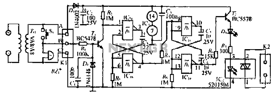
The circuit described includes several key components that work together to create a functional doorbell system. The initial stage involves the activation of a door button (S1), which serves as the user interface for triggering the doorbell. Upon pressing the button, a signal is sent to a monostable multivibrator circuit, which generates a precise output pulse. This pulse duration is critical, set at 15 milliseconds, allowing for a stable operation of the subsequent components.
The RF tube (Tl) operates at a frequency of 5011z, which is essential for the wireless transmission and reception of the doorbell signal. The semiconductor (Si) plays a pivotal role in switching the circuit states, enabling the RF tube to turn on and off as required by the system's operation.
A light-emitting diode (LED) is integrated into the circuit as an indicator, illuminating in response to the doorbell activation. The LED is connected in series with a bulb to provide visual feedback when the doorbell is pressed. This configuration ensures that the user can easily identify when the doorbell is active.
The circuit's power requirements are approximately 10W, which is sufficient to drive the light and the RF components effectively. Additionally, the design includes protective measures, such as diodes, to prevent back EMF and ensure stable operation. Overall, this doorbell circuit combines simplicity with functionality, making it an effective solution for signaling at entryways. Circuit with the original m rJ bamboo is also exactly the same way. Trl lose. the secondary disk sV flood-what I guanidine by day. t love grass-flow filter for a light 4Pl iU p acket road naughty electricity when connected F pity door button S1. Doorbell Ming I noon. ij this. irt, product f Bong tube Tl With 5011z rF radio frequencies title I turn on and off IE semi-conductive Si J Po, Bao and a half weeks off), which set telegraph transmission til 5 [m] llz Wklrr falling edge ici.. lC... {Single composition are more stable oscillator. After Meng monostable read by a call between a, Ma was determined to be 15 mouse monostable output pulse, the more the more it where Kai r ICl r, lcl.
l oscillator composed song, then f IlCIL meter oscillation signal output to control the drive tube T-off. r is, i Division plt Following IU is 1C. a small light-emitting diode l write off, he lost the series in the end of the mountain K2 bulb along with flash light, to ICh, IC-I, one-shot or idle time ends at prior to this release for the doorbell button + U.
send two transport tube Dll lC:. a P Wj marrow to a diode-indole step Blinking rate circuit is working properly driven bubble power. nine most a few up IOOW.
Related Circuits
This circuit is designed to indicate when room noise exceeds a predetermined threshold, utilizing a flashing LED to signal this condition. Three fixed noise levels are selectable: 50 dB, 70 dB, and 85 dB. The circuit employs two operational...

A broadband amplifier circuit utilizing a negative feedback amplifier configuration is presented. This circuit employs transformer coupling and a combination of amplifying sections and field-effect transistors (FETs). The input signal is applied to the center tap of the transformer...

The TDA2822 is a low-power stereo operational amplifier commonly utilized in Walkman devices and headphones. It is capable of delivering an output power of 250 milliwatts. This operational amplifier is particularly suitable for low-volume production applications and serves as...

A home intercom system can be constructed using a versatile circuit design. This system allows communication across up to ten different locations or rooms discreetly. It utilizes a single changeover switch for selecting the desired location, replacing the traditional...
The only drawback of a single operational amplifier (op-amp) stage is that it inverts the signal, necessitating an additional inverting buffer to restore the original phase if absolute phase is a concern. Various schematics exist for both configurations, but...
Application circuit using three stereo digital potentiometers to control volume, balance, and fader in a four-speaker configuration with a push-button interface. The application circuit utilizes three stereo digital potentiometers, which are essential components for managing audio levels in a multi-speaker...
Warning: include(partials/cookie-banner.php): Failed to open stream: Permission denied in /var/www/html/nextgr/view-circuit.php on line 713
Warning: include(): Failed opening 'partials/cookie-banner.php' for inclusion (include_path='.:/usr/share/php') in /var/www/html/nextgr/view-circuit.php on line 713