
0 To 12V, 1A Variable Power Supply Circuit
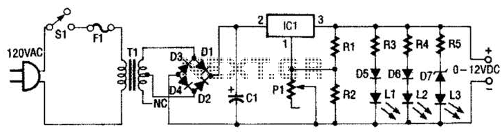
The 0- to 12-Vdc variable power supply design begins with a step-down transformer (T1), which converts the high voltage (120 V AC) from the mains to a lower voltage (28 V AC). This secondary output is then rectified and filtered to produce a smooth DC voltage. The rectification can be achieved using a bridge rectifier configuration, which typically consists of four diodes arranged to convert the AC voltage to pulsating DC. Following this, a large electrolytic capacitor is used to filter the output, reducing ripple and providing a stable DC voltage.
The heart of the power supply is the LM317T voltage regulator, which is a versatile adjustable three-terminal device. The input voltage at pin 2 is subjected to regulation, ensuring that the output voltage at pin 3 remains stable and within the desired range. The adjustment pin (pin 1) is connected to a resistor (R1), which allows for the output voltage to be set between 1.25 V and 12 V. By varying the resistance of R1, the output voltage can be fine-tuned according to the requirements of the load.
To provide an output voltage indication, the circuit employs a series of diodes (D5-D7) and light-emitting diodes (L1-L3). These components are strategically placed to light up in accordance with the output voltage level, giving a visual representation of the voltage being supplied. Each LED or diode path is equipped with a current-limiting resistor to prevent excessive current flow, ensuring the longevity and proper functioning of the indicators.
This configuration offers an efficient and reliable solution for applications requiring a variable DC power supply, making it suitable for a variety of electronic projects and testing environments. The design emphasizes safety and functionality, providing users with a robust tool for powering their electronic devices. This 0- to 12-Vdc variable power supply uses an IC voltage regulator and a heavy-duty transformer to provide a reliable dc power supply. Looking at the schematic shown, you can sec that transformer Tl has a 120-V primary and a 28-V secondary.
Filtered dc is fed to the input (pin 2) of the LM317T voltage regulator, IC, which keeps the voltage at its output constant (pin 3) regardless (within limitations) of the input voltage. Pin 1 of the LM317T is the adjustment pin. Varying the voltage on pin 1 (via PI) varies the output voltage. Diodes D5 through D7 and LEDs LI through L3 give an approximate indication of the output voltage. Each LED/diode path has a limiting resistor to limit the current to a level that is safe for the LED. 🔗 External reference
Related Circuits
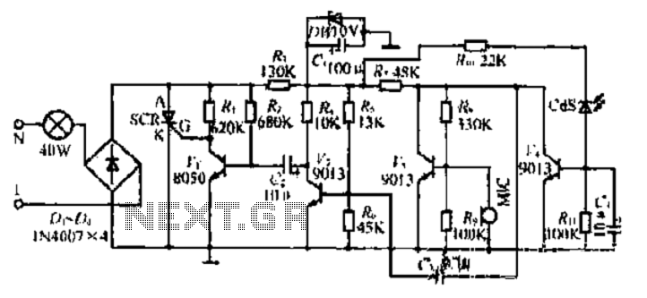
A touch dimmer circuit is illustrated in the accompanying diagram. It utilizes a finger touch control piece to enable the turning on, off, or stepless adjustment of incandescent lighting. This circuit is applicable in dimming filament lamps and for...
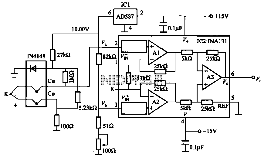
The AD587 is a precision voltage reference providing a 10 V output, generated using a 27 kΩ resistor along with a compensation diode (1N4148) and a thermocouple. This setup connects to the VI + N terminal of a differential...
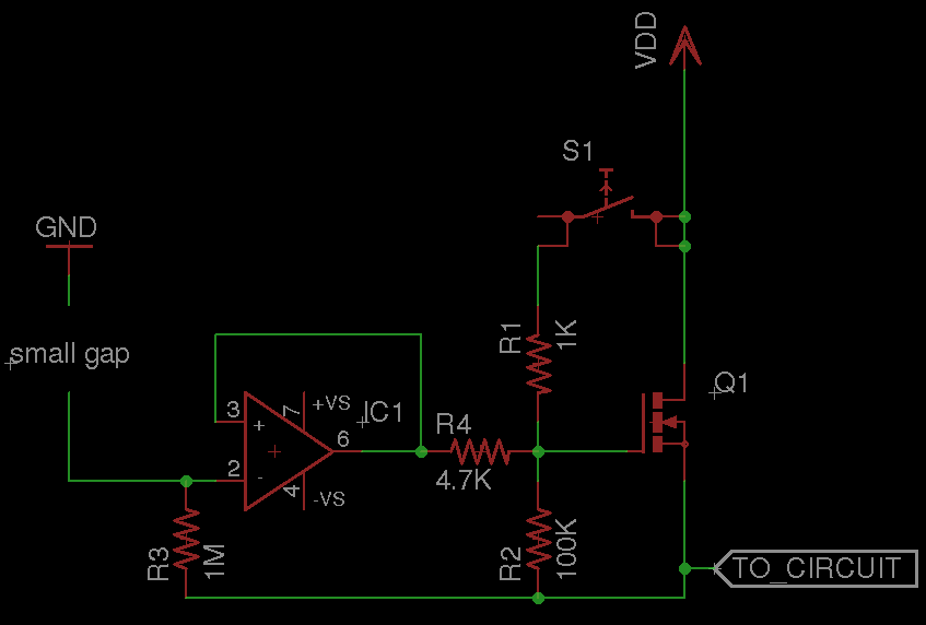
A circuit that requires protection from high voltage. Is there a component other than a fuse that does not need to be replaced every time? Something like a switch that activates only when high voltage is supplied, diverts the...
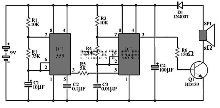
The circuit utilizes IC1 to create an astable multivibrator configuration. It is designed to generate a low-frequency output of approximately 1 Hz at pin 3, which is determined by the resistor values R1, R2 and capacitor C1. The output...
120V galvanic acupuncture salmon RI. The system features a wind-down rectification and a limit irrigation mechanism to achieve an amplitude of 24V. It includes isolation diodes and a steady stream over the circuit. The design ensures that a voltage...
This circuit turns off an amplifier or any other device when it remains idle for 15 minutes. It is powered by the amplifier's tape output. The described circuit functions as an automatic power management system, designed to enhance energy efficiency...