
1,5-15V 500mA Power Supply
The described variable power supply circuit is designed for low-cost applications while providing a range of output voltages from 1.5 V to 15 V, with a maximum current output of 500 mA. The circuit employs a potentiometer (P1) to allow for adjustable output voltage, enabling users to set the desired voltage level within the specified range. The stability of the output voltage is maintained within a tolerance of 2% as long as the load current remains below 350 mA, ensuring reliable performance for various applications.
The operational mechanism involves a feedback control system where transistor T4 monitors the voltage at the P1 slider compared to the output voltage. If the slider voltage exceeds the output voltage by 0.65 V, transistor T2 is triggered to open, effectively cutting off the base current to the Darlington pair formed by transistors T3 and T5. This configuration helps to regulate the output voltage by controlling the current flow through the power transistors, thus preventing over-voltage conditions.
The input power to the circuit is provided by an 18V, 1A transformer, which requires filtering to smooth out the rectified voltage. Capacitor C1 and diode B1 are employed for this purpose, ensuring that the output voltage remains stable and free from ripple.
In the event of an overload condition, where the output current exceeds 500 mA, an alarm is activated by buzzer Bz1. This buzzer is specified to operate at 24 V and is of the auto-oscillating type, providing an audible signal to alert users of the overload condition. This feature enhances the safety and usability of the power supply circuit, making it suitable for various electronic projects and applications where adjustable and stable voltage is required.This simple variable power supply circuit has a low production cost and delivers an output voltage between 1,5 V and 15 V with a 500 mA maximum current. Its stabilization is better than 2% if the current consumption do not exceed 350 mA. The variation of the power supply voltage can be made with a potentiometer and when overloading occurs a buzzer sounds a alarm.
T4 compairs the P1 slider voltage with the output voltage. Then the P1 slider voltage is 0,65 V higher than the adjusted voltage, T2 opens, which stops the T3-T5 Darlington base current. The 18V, 1A transformer voltage must be filtered with B1 and C1. When the output current is more then 500 mA, the Bz1 starts the alarm (overloading). Bz1 must be a 24 V type, auto-oscillating. 🔗 External reference
Related Circuits
The following diagram represents a 20W power amplifier circuit constructed using the EL34 tube component. The EL34 is a well-known tube that is highly regarded for use in power tube amplifiers. The circuit includes both the tube amplifier schematic...

The value of capacitor C2 can be selected to achieve the desired level of smoothness, as its capacitance is effectively amplified by the combined gains of transistors Q1 and Q2. For instance, if a capacitance of 100 µF is...
Occasionally, a low voltage power supply capable of delivering very high currents (hundreds of amperes) is required for applications such as spot welding, heating or melting metals, starting vehicle engines, or conducting various physical experiments. A decision has been...
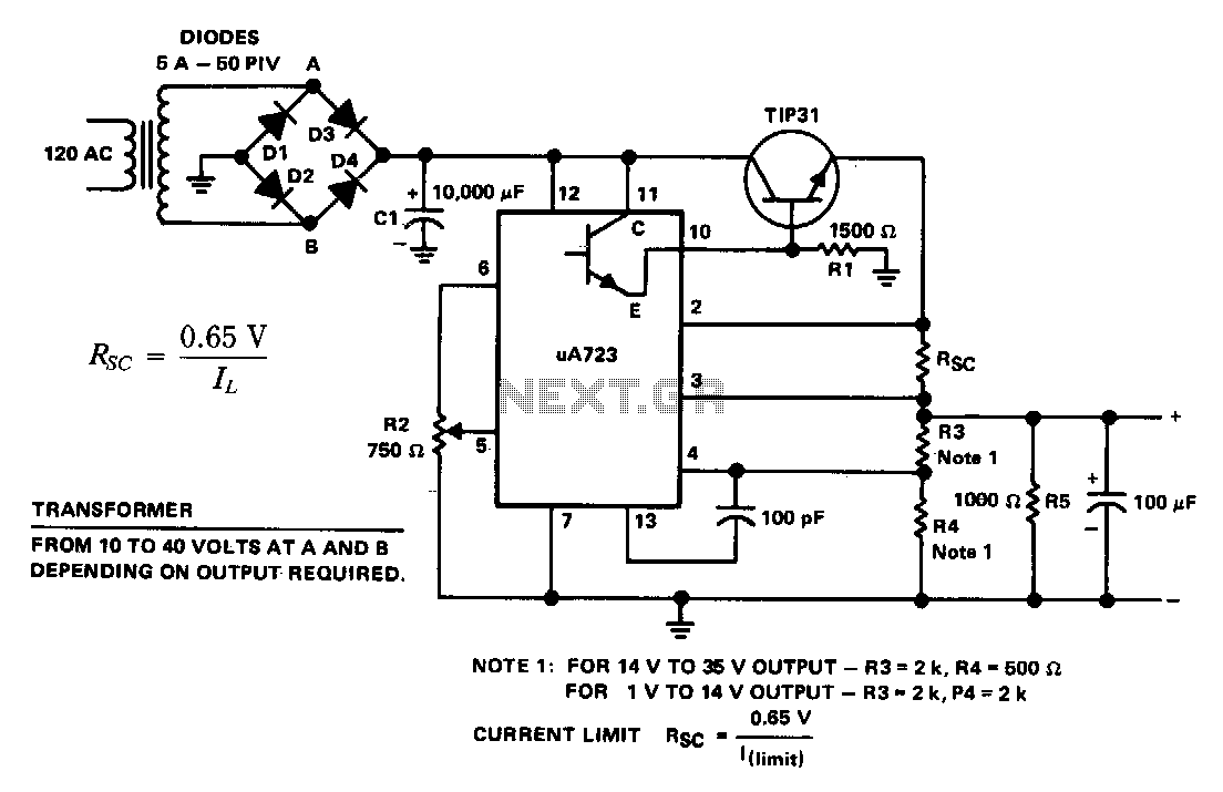
The supply 6-66 can be utilized for output voltages ranging from 1 to 35 V. The line transformer must be selected to provide approximately 1.4 times the desired output voltage from the positive side of filter capacitor C1 to...
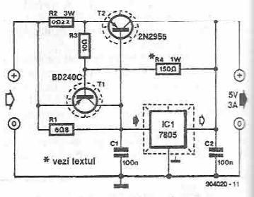
This power supply circuit is designed to provide a high current 5-volt output using a 7805 voltage regulator along with several standard electronic components. The transistor T1 functions as a current limiter. When the voltage across resistors R2 and...
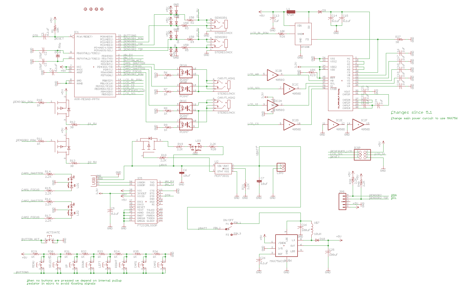
Previously, a linear regulator was used, but a Max756 boost converter is now in operation. An output ripple of 0.1 to 0.3V is observed in the current, while the Max756 datasheet indicates an expected ripple of about 50 mA....