
5 volts high current power supply using 7805 voltage regulator
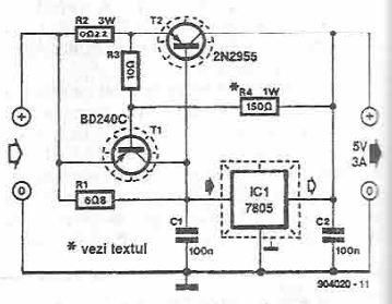
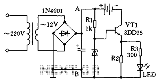
This power supply circuit utilizes a 7805 voltage regulator, which is a popular choice for providing regulated 5V output. The 7805 requires an input voltage that is typically higher than 7V to ensure proper regulation. The circuit's design incorporates T1 as a current limiting device to protect against excessive current draw. When the voltage across R2 and R3 reaches the threshold of 0.6 to 0.7 volts, T1 switches on, effectively cutting off the base current to T2. This action prevents T2 from turning on, which would otherwise allow more current to flow through the circuit.
The arrangement of resistors R2 and R3 is critical, as they are responsible for monitoring the voltage levels and ensuring that the current remains within safe limits. The voltage divider formed by resistors R3 and R4 is essential for establishing the correct biasing conditions for T2, allowing it to function properly within the circuit. This configuration ensures that T2 only activates when the voltage levels indicate that it is safe to do so, thus providing an additional layer of protection for the entire power supply circuit.
Overall, this circuit is an efficient solution for applications requiring a stable 5V power supply with built-in current limiting features, making it suitable for various electronic devices and projects.This power supply electronic circuit is a high current 5 volts power supply circuit that use a 7805 voltage regulator and some classic electronic components. T1 acts as a current limiter. Once the voltage on R2 + R3 is greater than 0. 6 0. 7 V, the transistor opens, which will reduce to zero the current in the base of T2. Voltage from which enters i n operation the protective circuit is given by the sum of drops voltage on the R2 and R3. Resistors R3 and R4 form a voltage divider on T2. 🔗 External reference
Related Circuits
The success or failure of lighting upgrades depends on the quality of components and workmanship. Proper wire routing is essential to prevent insulation chafing. The quality of soldering connections is crucial, as poor solder joints can corrode and fail....
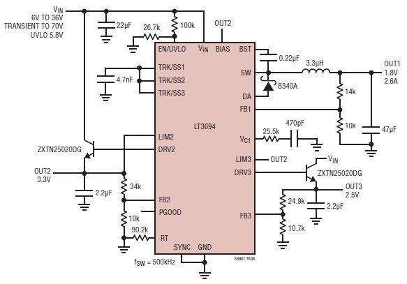
The LT3694 is a monolithic, current mode DC-DC converter that can be designed as a simple step-down converter, supporting a maximum output current of 2.6 A. This switching step-down converter is capable of generating up to 2.6 A at...
The telephone ring generator shown below generates the needed high voltage from a simple switching mode power supply (SMPS) which employs a CMOS Schmitt Trigger square wave oscillator, 10 mH inductor, high voltage switching transistor (TIP47 or other high...
A practical single-tube constant current charger is illustrated, utilizing a transistor (VT1) that plays a crucial role in maintaining a constant current. The current value is determined by the voltage regulator and resistor R2. The general output voltage is...
This application note demonstrates a simple 8-direction digital compass application utilizing Zilog's Z8 Encore!® MCU and an external compass sensor hardware. Communication ports are provided for the digital compass to receive commands and send status via the I2C bus...
This circuit functions as a camera switch, allowing multiple cameras to be connected to a single monitor. It can operate in both manual and automatic modes. In automatic mode, the circuit utilizes a 555 astable multivibrator to generate a...
Warning: include(partials/cookie-banner.php): Failed to open stream: Permission denied in /var/www/html/nextgr/view-circuit.php on line 713
Warning: include(): Failed opening 'partials/cookie-banner.php' for inclusion (include_path='.:/usr/share/php') in /var/www/html/nextgr/view-circuit.php on line 713