
1 KHz Sine Wave Generator Circuit

The circuit employs a Wien bridge oscillator configuration, which is renowned for its ability to produce low-distortion sine waves. The inverted design allows for enhanced stability and control over the output characteristics. The selection of capacitors C1 and C2, along with the resistors R3 and R4, is critical in setting the desired frequency of oscillation. The values of C1 and C2 directly influence the frequency; thus, careful selection is necessary to achieve the target frequency of 1 kHz.
The bulb serves as a variable resistor that helps stabilize the oscillation by providing feedback. The specific current ratings for the bulb are crucial; using a bulb outside the specified range may lead to instability and increased distortion. The adjustment of R6 is an essential step if the bulb specifications are altered, as it ensures that the feedback loop remains effective.
R5 is used to calibrate the output voltage, and its adjustment is vital for achieving the desired output level. The use of an audio millivoltmeter allows for precise measurement, while an oscilloscope can visualize the waveform, confirming its sine wave characteristics and amplitude.
The recommendation for high-gain transistors is based on their ability to amplify the signal effectively, thereby improving the overall performance of the oscillator circuit. This choice enhances the circuit's efficiency, allowing it to maintain low distortion levels across various output conditions.
In summary, this circuit design is a robust solution for generating a low-distortion sine wave, suitable for various applications requiring stable frequency output. Proper component selection and adjustments are critical to achieving optimal performance.This is a design circuit for generates a good 1 KHz sine wave adopting the inverted Wien bridge configuration (C1-R3 & C2-R4). It features a variable output, low distortion and low output impedance in order to obtain good overload capability.
The figure is shown in below. The bulb must be a low current type (12V 40-50mA or 6V 50mA) in order to obt ain good long term stability and low distortion. Distortion @ 1V RMS output is 0. 15% using a 12V 40mA bulb, raising to 0. 5% with a 12V 100mA one. Using a bulb differing from specifications may require a change of R6 value to 220 or 150 Ohms to ensure proper circuits oscillation. Set R5 to read 1V RMS on an Audio mili voltmeter connected to the output with R7 rotated fully clockwise, or to view a sine wave of 2.
828V Peak-to-Peak amplitude on the oscilloscope. With C1, C2 = 100nF the frequency generated is 100Hz and with C1, C2 = 1nF frequency is 10 KHz but R5 requires adjustment. High gain transistors are preferred for better performance. 🔗 External reference
Related Circuits
This document outlines the theory behind a high-speed control scheme for an LED display screen circuit. The circuit utilizes the MCS51 series microcontroller to manage the LED display. A 62512 random access memory (RAM) is employed for data storage,...
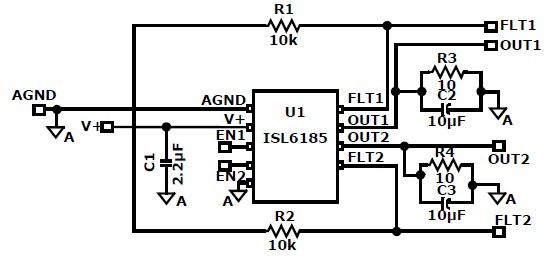
The ISL6185 USB power controller family can be utilized to design a straightforward USB power supply electronic project that offers fully independent overcurrent (OC) fault protection for two or more USB ports. This product family includes sixteen distinct functional...
A neon lamp or tube lamp requires high voltage to initiate the ionization of the gas contained within the tube. Once ionization takes place, the voltage decreases to approximately 40 volts. Neon lamps operate on the principle of gas discharge,...
An extremely simple and low cost Sine/Square wave generator based on the Analog Devices AD9835 Direct Digital Synthesis (DDS) Generator chip. The frequency can be set for any frequency from 1Hz to 10MHz in 1Hz resolution steps! All this...
This project features a schematic for a touch alarm circuit. The circuit is highly sensitive and activates a piezo buzzer or any other type of buzzer, along with an LED, for a predetermined duration when a metal plate is...
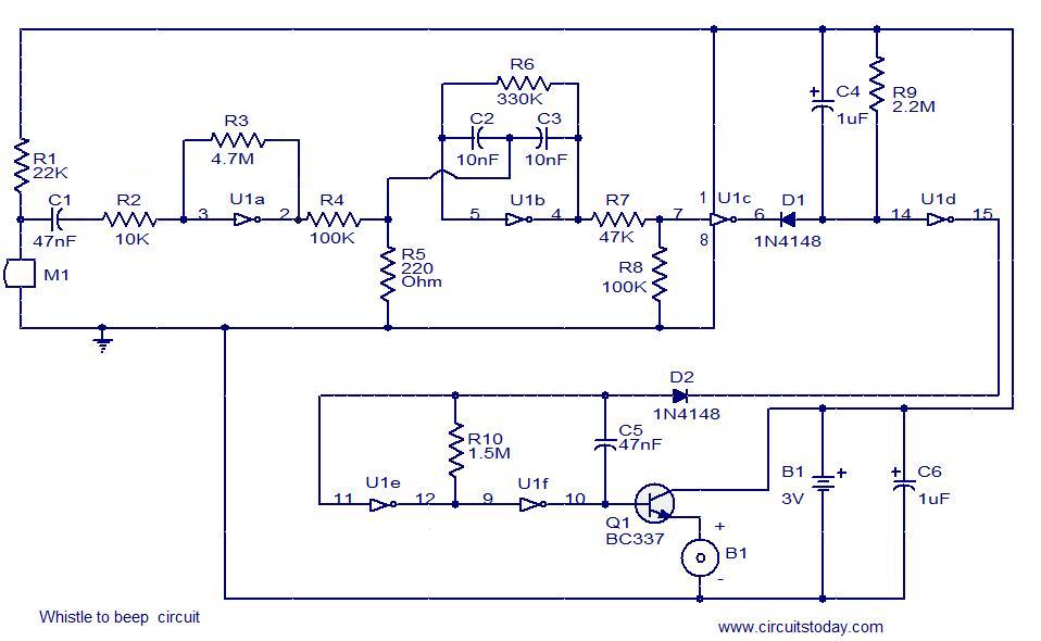
This simple circuit produces a beeping sound that lasts for approximately 3 seconds whenever a whistle is made. The CMOS Hex inverter CD4049 serves as the core component of this circuit. Among the six inverters in the CD4049, U1a...