
1 KW Watt Meter

This watt-meter circuit is designed to accurately measure electrical power in AC circuits, specifically within a range of up to 1 kW. Utilizing a single transistor, the circuit is capable of performing both voltage and current measurements, thus enabling the determination of true power (measured in Watts) delivered to the load. The operational voltage range of 117 Vac ± 50 Vac makes it suitable for standard household and industrial applications, while the potential for modification allows adaptability for lower voltage scenarios.
The circuit's focus on measuring power during negative cycles is noteworthy, as it can enhance accuracy in certain applications where reactive power may not be a primary concern. One of the significant advantages is the absence of a need for an external power supply, making it efficient and easy to integrate into various systems.
The idle power consumption of only 0.5 W indicates a low-energy footprint, which is beneficial for energy-conscious designs. The load current sensing voltage of 10 mV ensures that even small variations in current can be detected, while the minimal load voltage loss of 0.01% indicates high efficiency in the measurement process.
The circuit exhibits excellent performance with linear loads, boasting a rejection ratio of reactive load currents greater than 100:1. This characteristic is crucial in applications where accurate power measurement is required in the presence of reactive components. The nonlinearity specification of approximately 1% at full scale when using a 50 A meter movement suggests that the circuit maintains a high degree of accuracy across its operational range.
For temperature compensation, the use of a copper shunt is recommended. This component helps to maintain the accuracy of the current measurement under varying thermal conditions, ensuring that the circuit remains reliable in diverse environments. Overall, this watt-meter circuit design represents an effective solution for measuring electrical power with a focus on accuracy, efficiency, and adaptability.This watt-meter circuit has measurement range up to 1-KW. This circuit can give the complete (X)(Y) function although uses only one transistor. Actually, this circuit is used for 117 Vac ±50 Vac operation. For lower or lower voltage, this circuit can be modified easily. This circuit only measure power on negative cycles. The advantages of this cir cuit is this circuit does not need external power supply. This circuit measures true power that is delivered to the load. Here is the schematic diagram of the circuit: At idle section, this circuit draw only 0. 5W. This circuit has load current-sensing voltage of 10mV and load voltage loss of 0. 01%. For linear loads, Rejection of reactive load currents is better than 100:1. When using a 50- A meter movement, the nonlinearity of this circuit is about 1% full scale. Copper shunt can be used to give correct gain due to temperature. [Circuit`s schematic diagram source: seekic. com] 🔗 External reference
Related Circuits
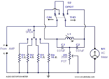
This is a simple 1 kHz audio distortion meter designed to measure the Total Harmonic Distortion (THD) on any load at any output power. The circuit allows for the selection of load impedances of 2, 4, 8, or 16...
This simple add-on capacitance meter has been specially designed to help you identify capacitors from 1p to 10u. There has always been a problem identifying capacitors, due to the enormous variety in size, shape and coding. Most of the...
This design utilizes a well-established circuit topology for the power amplifier, employing a single-rail supply of approximately 60V and capacitor coupling for the speaker(s). The benefits for a guitar amplifier include a straightforward circuit design even at relatively high...
This is a small but quite powerful FM transmitter having three RF stages incorporating an audio preamplifier for better modulation. It has an output power of 4 Watts and works off 12-18 VDC which makes it easily portable. It...
This circuit, housed in a compact plastic enclosure, is designed for portability and can be easily placed inside a bag or handbag. A small magnet is positioned near a reed switch and is attached to the individual carrying the...
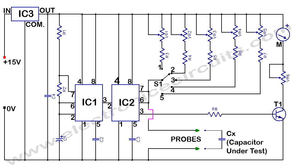
Capacitance Meter Circuit Using 555. It directly reads capacitance in the range of 100 pF to 10 µF. IC1 and IC2 operate as an astable multivibrator, generating a frequency that is dependent on the capacitance being measured. The capacitance meter...