
Audio Distortion Meter Circuit with Diagram
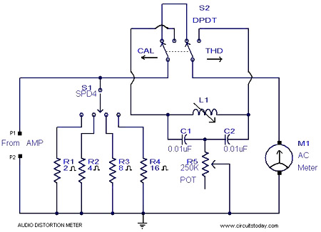
The audio distortion meter is structured around a notch filter configuration that effectively isolates the fundamental frequency while attenuating harmonic frequencies. The selection of load impedance is facilitated through a switch or jumper settings that connect the appropriate resistive load to the circuit. The notch filter, composed of an inductor (L1) and capacitors (C1 and C2) in conjunction with a resistor (R1), is designed to create a deep attenuation at the 1 kHz frequency. This allows for precise measurement of the THD by comparing the output signal to the input signal.
To implement the circuit, the 1 kHz signal can be generated either by a dedicated signal generator or by constructing a Colpitts oscillator, which utilizes a combination of capacitors and an inductor to produce a stable sine wave output at the desired frequency. The oscillator circuit typically includes a transistor configured in a feedback loop to ensure consistent oscillation.
Once the input signal is fed into the amplifier under test, the output can be connected to a measurement device, such as an oscilloscope or a spectrum analyzer, to analyze the distortion characteristics. The difference between the fundamental frequency and the harmonics will provide a quantitative measure of the THD, which can be calculated using the ratio of the power of the harmonics to the power of the fundamental frequency. This process enables engineers and technicians to evaluate the performance of audio amplifiers and ensure that they meet the required specifications for audio fidelity.Here is a simple 1KHz audio distortion meter that can measure the Total Harmonic Distortion (THD) on any load at any out put power. Here you have the option to select 2, 4, 8 or 16 Ohm loads. The circuit works by filtering the 1 kHz fundamental signal using a notch filter comprising of L1, C2, C1, R1.
With a little time and calculation you can get the c orrect THD of your amplifier in such a simple way. Feed the input of your amplifier a 1KHz signal from a signal generator. If you don`t have a signal generator make a 1 kHz Colpitts oscillator for the purpose. 🔗 External reference
Related Circuits
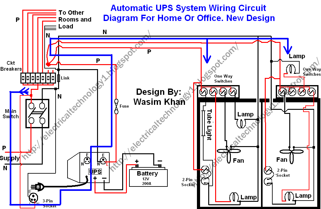
This wiring circuit diagram is designed for providing power to specific rooms in a home or office during a power supply failure. It ensures continuous power supply to devices such as laptops and computers in those particular rooms, especially...
This is a simple proximity switch utilizing the IC 4049. The IC 4049 is a bipolar monolithic integrated circuit designed for metal detection systems and proximity sensing applications. It includes an oscillator formed by an external parallel resonant tank...
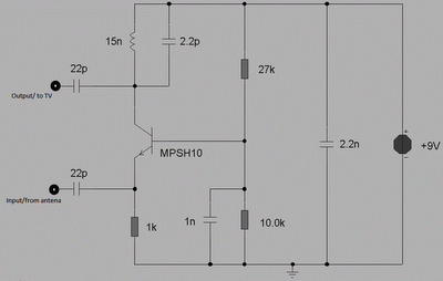
This circuit is designed to enhance RF signals from a television antenna operating at UHF frequencies in the range of 450-800 MHz. It provides a gain of approximately 10 dB, making it suitable for boosting weak TV signals. The...
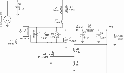
It employs a low threshold MOSFET and two coupled coils to function as a joule thief. An additional MOSFET is utilized for regulation. The circuit operates as a joule thief, which is a type of DC-DC converter designed to extract...
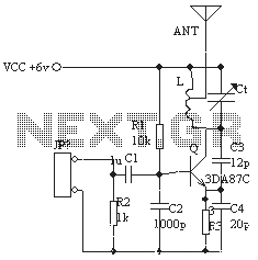
The ordinary triode 3DA87C is utilized to create a long-range FM transmitter circuit, which functions as a standard three-point oscillator circuit. This remote transmitter circuit is capable of large current emissions, achieving a range of up to 1 kilometer...
The circuit is designed to operate with an audio power amplifier that uses 18V-0V-18V power rails. The specific voltage is not critical, but the feedback is referenced to an LED chain connected to a 12V rail, necessitating a separate...
Warning: include(partials/cookie-banner.php): Failed to open stream: Permission denied in /var/www/html/nextgr/view-circuit.php on line 713
Warning: include(): Failed opening 'partials/cookie-banner.php' for inclusion (include_path='.:/usr/share/php') in /var/www/html/nextgr/view-circuit.php on line 713