
10 watt rf amplifier for 18mhz by

The circuit comprises two linear amplifier stages, each designed to enhance the signal strength while maintaining signal integrity. The input stage receives a 0.55-watt RF signal, which is then amplified by the first linear amplifier. This stage typically employs a transistor or an operational amplifier configured in a linear mode to ensure minimal distortion. The output of this stage is then fed into the second linear amplifier, where further amplification occurs to achieve the desired 10-watt output.
The choice of components is crucial for achieving optimal performance. High-frequency transistors with low noise figures should be selected to minimize signal degradation. Additionally, the use of appropriate biasing resistors and capacitors is essential to maintain stability and linearity across the operating frequency range. The circuit should also include bypass capacitors to filter out any unwanted noise and ensure a clean power supply to the amplifiers.
Thermal management is another important consideration. Adequate heat sinking should be provided for the transistors to prevent thermal runaway, which could lead to damage or reduced performance. The layout of the circuit board should be designed to minimize parasitic inductance and capacitance, which can adversely affect the performance of high-frequency amplifiers.
The power supply for this project is specified at 12 volts DC, which is a common voltage level that can be easily sourced from batteries or power adapters. Care should be taken to ensure that the power supply can provide sufficient current to support both amplifier stages without sagging, as this could lead to distortion in the output signal.
In conclusion, this project not only enhances the output power of QRP transmitters but also serves as an educational platform for understanding linear amplifier design principles. The resulting amplifier will significantly improve communication capabilities in marginal radio conditions, making it a valuable addition to any amateur radio operator's toolkit.This project and your efforts will provide you with a 0. 55 3 watt input to easily 10 watt output. The two linear amplifiers are ment for use with QRP SSB/CW/FM/AM transmitters on the amateur bands 15 and 17 meters can be powered from a 12 volt DC supply. The design is a good balance between output power, physical size. The completed amplifier wi ll reward the builder with a clean, more powerful output signal for a QRP rig when radio conditions become marginal. 🔗 External reference
Related Circuits
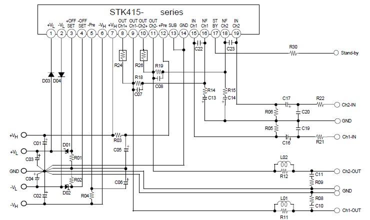
This electronic project stereo amplifier is based on the STK415-090-E class H audio power amplifier hybrid integrated circuit (IC), which includes a built-in power supply switching circuit. The STK415-090-E class H audio power amplifier achieves high efficiency in audio...
Every electronic device that boosts electrical signals can be called an amplifier. The various amplifier types only differ in some specific features. Amplifiers are crucial components in electronic circuits, designed to increase the amplitude of electrical signals. They play a...

The AN41240A is a single-chip integrated circuit (IC) designed for audio applications. It employs a single-hall-sensor drive on the input side of the spindle motor drive block and utilizes a low-noise direct PWM drive of sine wave on the...
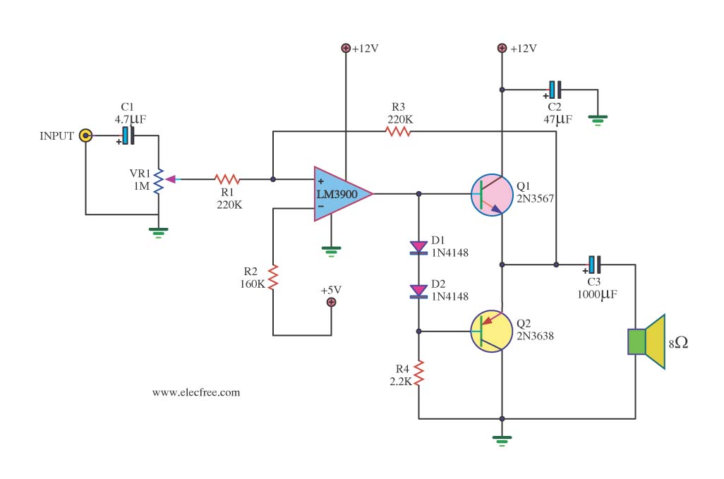
This is a mini-sized power amplifier rated at 2 watts OTL that utilizes the LM380 integrated circuit. It serves as a ready-made circuit for audio applications and communication, requiring minimal external equipment. The capacitor C6 can be selected from...
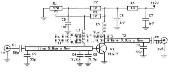
This amplifier is designed to amplify RF signals from an antenna by 10 dB and operates as a Class A amplifier using the BFQ34 transistor from Philips. The BFQ34 is packaged in an SOT122A case. The BFQ34T variant is...
When the amplifier is installed inside the suitcase, it will require a change to stop working. The LA47536 has a control pin (pin 4) that requires a small voltage of up to 2V to turn on the amplifier. Transistors...