
TV signal amplifier 470Mhz-860Mhz
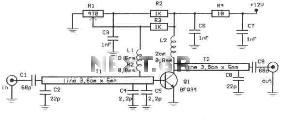
This RF amplifier circuit employs the BFQ34 transistor, which is suitable for low-noise amplification in RF applications. The Class A configuration ensures that the transistor operates in the linear region, providing consistent amplification without significant distortion when the input signal is within the specified range. The choice of a 10 mW input signal is optimal for achieving the desired gain while maintaining signal integrity.
The BFQ34 transistor, with its SOT122A package, allows for efficient thermal management and compact design, essential for RF applications where space is limited. The recommendation against using the BFQ34T variant is critical, as different transistor characteristics can lead to suboptimal performance or even circuit failure.
The power supply requirement of 12 volts and 1 amp is crucial for ensuring that the transistor operates correctly without entering saturation or cutoff regions, which would compromise the amplifier's performance. A regulated power supply is advised to maintain a stable voltage under varying load conditions.
To prevent signal distortion, it is imperative to monitor the input levels and ensure they do not exceed the specified limits. Overdriving the transistor can introduce unwanted harmonics and reduce the overall fidelity of the amplified signal.
Enclosing the circuit in a metal box serves multiple purposes, including shielding against electromagnetic interference (EMI) and providing physical protection for the components. The enclosure should be designed to allow for adequate ventilation to dissipate heat generated by the transistor during operation. Proper grounding techniques should be employed within the metal box to minimize noise and ensure reliable operation of the amplifier.This amplifier can amplify to 10dB the RF signal from antenna working as class A and is based on transistor BFQ34 of Philips. The transistor comes in case SOT122A. You may find the BFQ34T in market but better do not use it as it has different characteristics. Input signal should be about 10mW if we want 10dB output. So with 0.5mW we get 5dB. Do not overdrive the transistor because the signal will be distorted full of lines, without color etc. So use 12Volts with 1A stabilised power supply. The circuit should be enclosed in a small metal box. 🔗 External reference
Related Circuits
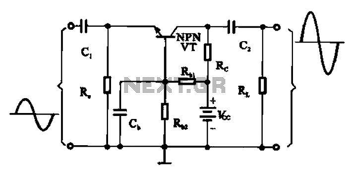
A common base transistor amplifier circuit is characterized by its basic structure, which includes key components such as a biasing resistor, capacitors for coupling, and an amplifying transistor. The circuit features four resistors that establish the quiescent point, with...
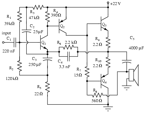
Note that Q3 and Q4 in the figure below are complementary, with Q3 being an NPN transistor and Q4 being a PNP transistor. This circuit is suitable for moderate power audio amplifiers. For a detailed explanation of this circuit,...

This cool-down relay circuit utilizes an integrated circuit (IC) timer to control a relay, which maintains the operation of the blower for a specified time delay determined by timer U3. The capacitance value of C2 can be adjusted to...
Here is a little audio amplifier similar to what you might find in a small transistor radio. The input stage is biased so that the supply voltage is divided equally across the two complimentary output transistors which are slightly...
The mixer is the common "virtual earth" mixing amplifier, and there is nothing special about it. Note that it is inverting, which complements the tone controls (also inverting) so the absolute signal polarity is maintained. As shown, the mixer...
.png)
The one-touch turn signal (OTTS) module enhances the functionality of the turn signal lever by introducing a mode where a single touch activates the indicators to blink for a specified number of times. This feature is commonly referred to...