
100MHz Varicap Oscillator

The 100 MHz Varicap Oscillator circuit is designed to generate high-frequency signals suitable for various modulation applications. The core component of this circuit is the varicap diode, which functions as a voltage-controlled capacitor. By varying the reverse bias voltage applied to the varicap, the capacitance changes, allowing for the tuning of the oscillator frequency.
The oscillator typically employs a Colpitts or Hartley configuration, which utilizes inductors and capacitors to establish the resonant frequency. In this case, the circuit is optimized to operate at a frequency of 100 MHz. The modulation signals produced can reach a maximum amplitude of less than 28 V, making the circuit suitable for interfacing with other electronic components or systems.
Frequency deviation is a critical parameter in modulation schemes, and this circuit is capable of achieving a peak-to-peak frequency deviation of 28 MHz. This allows for effective modulation of the carrier signal, which is essential in applications such as frequency modulation (FM) transmission.
The circuit design may also incorporate additional components such as amplifiers and filters to enhance signal integrity and ensure stable operation across the desired frequency range. Proper biasing and impedance matching techniques are necessary to maintain optimal performance and minimize signal distortion.
Overall, the 100 MHz Varicap Oscillator circuit is a versatile solution for generating high-frequency modulation signals, suitable for various communication and signal processing applications.This is a 100MHz Varicap Oscillator circuit. This circuit can provide modulation signals less than 28V and frequency deviation of 28 MHz peak-to-peak. This . 🔗 External reference
Related Circuits
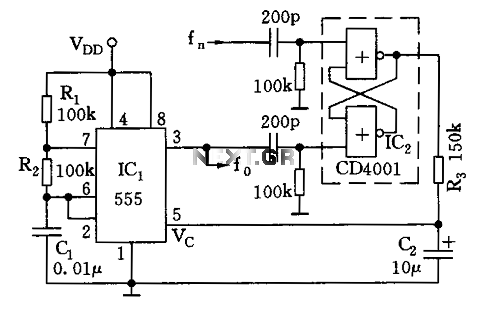
The circuit illustrated consists of a 555 timer along with resistors R1 and R2, and capacitor C1, forming a composition-controlled multivibrator. The oscillation frequency is influenced not only by the RC time constant but also by the adjustment of...
The Hartley Oscillator is characterized by an LC circuit in its collector. The base of the transistor is held steady, and a small amount of signal is taken from a tapping on the inductor and fed to the emitter...
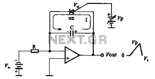
A sawtooth voltage-controlled oscillator operates by first generating a negative potential maximum at the output of the comparator. This output is then fed to the inverting input terminal through resistor R1, which is part of the relaxation oscillator. The...
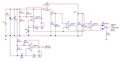
The goal is to control the speed of a 6-volt brush DC motor using a linear potentiometer and to create an oscillating speed effect, with the oscillation frequency also adjustable via a linear potentiometer. The desired complete cycle peak-to-peak...
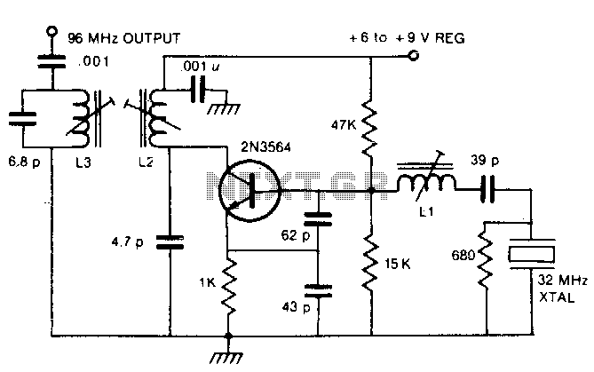
By utilizing a crystal oscillator operating between 27 and 33 MHz, the third harmonic frequency will produce an output ranging from 82 to 99 MHz. The implementation of a crystal oscillator within the specified frequency range of 27 to 33...
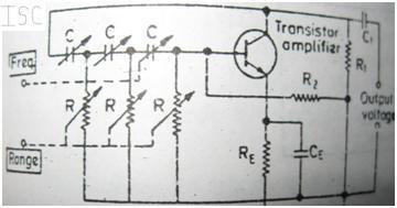
A complete description is provided for generating the required frequency using the phase shift method, along with its advantages and limitations compared to the Wien bridge method of oscillations. The complete circuitry of the phase shift oscillator is illustrated...