
Phase shift and Wiens bridge oscillator
The phase shift oscillator operates based on the principle of providing the necessary phase shift to achieve sustained oscillations. The fundamental configuration comprises an operational amplifier (op-amp) that serves as the active element, with its feedback network composed of resistors and capacitors. The phase shift required for oscillation is achieved through a combination of these components, typically arranged in a cascaded format to yield the desired total phase shift.
In the case of a three-stage phase shift oscillator, each stage typically consists of a resistor and capacitor in series, creating a low-pass filter effect. The phase shift introduced by each stage is approximately 60 degrees, summing to a total of 180 degrees when the output is fed back to the inverting input of the op-amp. This feedback loop is crucial for maintaining oscillation, as it ensures that the output signal is in phase with the input signal at the specified frequency, thus sustaining the oscillation.
The frequency of oscillation can be determined using the formula:
\[ f = \frac{1}{2\pi R C \sqrt{6}} \]
where \( R \) is the resistance and \( C \) is the capacitance in the feedback network. This equation illustrates how the frequency can be adjusted by varying the resistor and capacitor values, allowing for flexibility in design.
Additionally, while the phase shift oscillator is generally simpler to implement than the Wien bridge oscillator, it does have limitations in terms of frequency stability and the effects of loading on the amplifier. At higher frequencies, the reactance of the capacitors decreases, leading to a reduced phase shift and potentially unstable oscillations. Therefore, careful consideration of component values and circuit layout is essential to optimize performance and achieve the desired frequency stability across the operational range.
In summary, the phase shift oscillator is a versatile and efficient design for generating sinusoidal waveforms, particularly suitable for low-frequency applications. Its simplicity and ease of implementation make it a popular choice in various electronic circuit designs.A complete description is given upon generation of required frequency by using phase shift method along with the advantages and limitation against Wien`s bridge method of oscillations. Complete circuitry of phase shift oscillator is illustrated to describe the concept of its operational principle.
Oscillator is basically an electronic device that produces an AC signal at the output upon the application of a DC input signal. The wave form of this AC signal can be set into any desired format but generally a sinusoidal wave is formed. Here we will see how a phase shift method can be used for production of oscillations in a DC voltage to get an oscillating signal of required frequency and characteristics.
As is clear from the heading these oscillators have two main components which are resistors and capacitors. These can be further classified under two sections which are: A simplified RC network is used in those cases when oscillator is to be used in a very small range of frequency or within a very narrow range of frequencies.
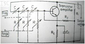
To show the basic circuit arrangement for a simple phase shift oscillator we can refer to the following figure shown below: This arrangement can be used for the purpose of regeneration of the frequency range of about a few hundred Hz. There is a signal amplifier stage in the circuitry. This amplifier is followed by a series of three resistors and capacitors connected in cascaded form. This circuit arrangement can be seen clearly in above figure. The function of this cascaded arrangement of resistors and capacitors is just to provide the required feedback to the amplifier stage.
As a single amplifier stage is employed in the circuitry it provides inversion of the input signal by 180 degree and this signal is obtained at its base. The RC network, as discussed above, provides the additional 180 degree inversion to this signal. At this is done only at a specific frequency range. Thus the frequency or the frequency range where RC network provide 180 degree inversion the total shift in phase input signal at base results in net zero phase shift i.
e. exactly equal to the original signal, means no inversion takes place for the concerned frequency range. This results in a very interesting conclusion that after application of negative feedback at base terminal does not reduce the amplification, but this only for the concerned frequency range.
There exists a phase shift network which consists of an operational amplifier and many resistors connected together such that the resistors and capacitors are of equal value and connection between them is of cascaded form. The combinations of resistors and capacitors occur to be in such a manner that they form some stages where each stage provide a phase shift of 60 degree such phase shift of two stages sums up to be phase shift of 180 degree.
There an effect is exhibited by an amplifier that is termed as andy loading effect. During analysis of this circuit se ignore andy loading effect of amplifier. And the expression of phase shift is calculated. The finalized expression occurs to be in complex form whose imaginary part comes to be zero when phase shift is of 180 degrees. It has very simple circuitry as compared with that of Wien`s bridge oscillator. This is because the circuitry involves a negative feedback arrangement associated with amplifier which is very easy to establish.
It is very easy to use it at a very wide range of frequencies that ranges form few Hz to several Hz. But a limitation the upper frequency limit is not so large because it high frequencies the impedance of RC network is very small at high frequencies so it is basically useful for lower frequencies. Low impedance of RC network also needs to heavy loading of amplifier. In order to avoid this situation a corrective measurement has t be made. This type of correction leads to complicated circuitry and the advantage of this type of method, whi 🔗 External reference
Related Circuits
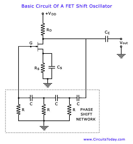
The phase shift oscillator is selected as an initial example as it clearly illustrates the principles discussed in the previous blog post. The circuit diagram emphasizes the amplifier and feedback network. It consists of a common source FET amplifier...
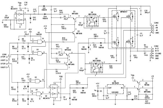
The following circuit illustrates an N-Channel H-bridge motor drive circuit diagram. Features include low voltage motor drives utilizing N-channel MOSFETs. The N-Channel H-bridge motor drive circuit is designed to control the direction and speed of a DC motor using low...
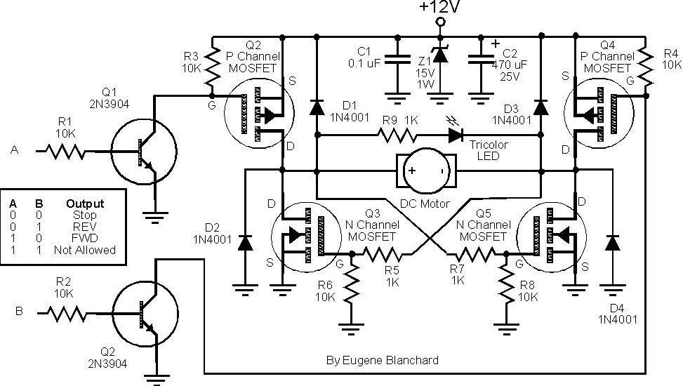
At 9 volts, the maximum stalled current of the motor types intended for use will be 700 mA. The selection of appropriate MOSFETs is crucial, particularly regarding their ratings for current and voltage handling. However, there are concerns about...
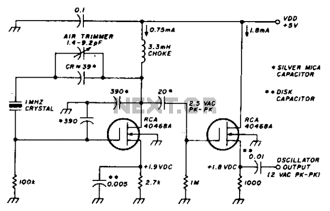
This stable oscillator circuit exhibits less than a 1 Hz frequency change over a VDD range of 3 to 9 volts. Stability is attributed to the use of MOSFET devices and stable capacitors. The described oscillator circuit is designed to...
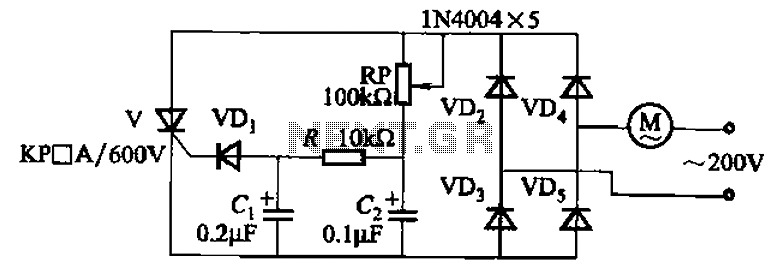
The circuit illustrated in Figure 3-11 employs a unidirectional thyristor control mechanism. An adjustable potentiometer, designated as RP, is utilized to continuously modify the motor speed. The circuit utilizes a unidirectional thyristor, also known as a silicon-controlled rectifier (SCR), which...

A 3D enhancement is required to achieve a fully three-dimensional sound experience for most stereo multimedia products. Typically, simple phase-delay circuits are utilized to create a widening effect on the perceived sound field. However, this approach can lead to...