
12 V battery charger
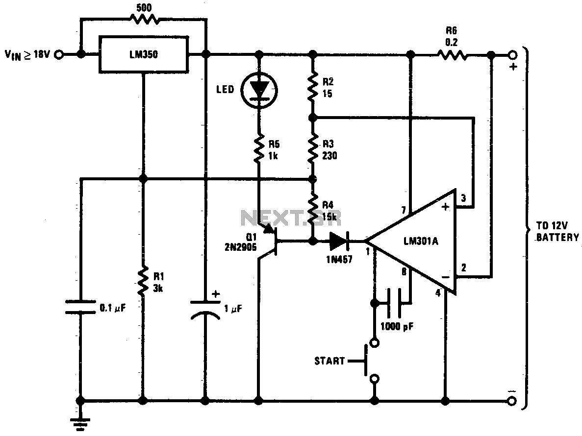
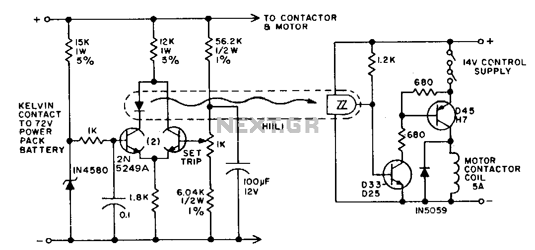
This high-performance charger circuit is designed specifically for gelled electrolyte lead-acid batteries, which are commonly used in various applications due to their reliability and efficiency. The circuit operates by initially supplying a constant current of 2A to the battery, ensuring a rapid recharge. This initial phase is crucial for quickly restoring the battery's capacity.
As the battery charges, its voltage increases, which in turn causes the charging current to decrease. This gradual reduction in current is essential for maintaining battery health and longevity. When the charging current falls to 150 mA, the circuit transitions to a float charging mode. This mode is characterized by a lower, stable output voltage that prevents overcharging, which can lead to battery damage.
The charger is activated by a start switch, which sets the output voltage to 14 V. This voltage is optimal for charging lead-acid batteries, ensuring effective energy transfer during the initial charging phase. As the battery approaches its full charge, the output voltage is carefully reduced from 14 V to approximately 12.5 V. This controlled decrease in voltage is critical for the safe termination of the charging process.
An important feature of this circuit is the use of a transistor (Q1) that serves as an indicator for the charging status. Once the battery reaches full charge, the LED connected to the transistor illuminates, providing a clear visual indication to the user. This feature enhances usability by allowing users to easily monitor the charging status without needing to measure the battery voltage directly.
In summary, this charger circuit combines efficient charging techniques with safety features to ensure the longevity and reliability of gelled electrolyte lead-acid batteries. Its automatic shut-off and visual indicators make it user-friendly and effective for various applications.This circuit is a high performance charger for gelled electrolyte lead-acid batteries. Charger quickly recharges battery and shuts off at full charge. Initially, charging current is limited to 2A. As the battery voltage rises, current to the battery decreases, and when the current has decreased to 150 mA, the charger switches to a lower float voltage preventing overcharge. When the start switch is pushed, the output of the charger goes to 14 V. As the battery approaches full charge, the charging current decreases and the output voltage is reduced from 14 V to about 12
5 V terminating the charging. Transistor Ql then lights the LED as a visual indication of full charge. 🔗 External reference
Related Circuits
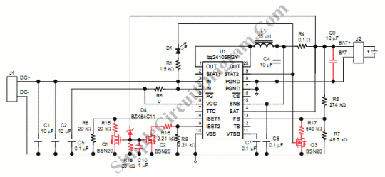
Switch mode circuits can implement a lead acid battery charger more efficiently. It can be constructed using the bq24105 battery charger controller. Switch mode power supplies (SMPS) are widely recognized for their efficiency and compactness, making them suitable for applications...
A designer often needs to know the internal resistance value of a battery. Many testers provide a relative indication of this value, but it is seldom expressed in ohms. The current tester can, in principle, provide this information. The...
The ASUS Eee is an ultra-portable notebook that meets the essential needs of tech enthusiasts while maintaining excellent build quality and affordability. In New Zealand, it can be purchased exclusively from DSE, where it is competitively priced compared to...
The battery life and operating cost of an electric vehicle are significantly impacted by the overdischarge of the battery. This circuit is designed to provide both a warning and a shutdown mechanism. An electronic switch is connected in series...

This is a single-zone alarm system featuring independently adjustable Exit, Entry, and Siren Cut-Off timers. It is compatible with standard normally-closed input devices such as magnetic-reed contacts, foil tape, and passive infrared sensors (PIRs). A mains power supply can...
A common requirement in many systems is to obtain both positive and negative supplies from a single battery. For applications with small current needs, the circuit illustrated provides a straightforward solution. It generates symmetrical output voltages of ±, each...
Warning: include(partials/cookie-banner.php): Failed to open stream: Permission denied in /var/www/html/nextgr/view-circuit.php on line 713
Warning: include(): Failed opening 'partials/cookie-banner.php' for inclusion (include_path='.:/usr/share/php') in /var/www/html/nextgr/view-circuit.php on line 713