
A Battery Powered Burglar Alarm With A Timed Siren Cut-Off

This single-zone alarm system is designed to provide effective security for residential or small commercial applications. The use of normally-closed input devices ensures that any breach in security will trigger the alarm, providing immediate notification of unauthorized access. The adjustable timers for Exit, Entry, and Siren Cut-Off enhance the system's flexibility, allowing users to customize the operation according to their specific needs.
The circuit's design incorporates a microcontroller or timer IC that manages the timing functions, ensuring accurate delays for each phase of the alarm operation. The use of a two-way switch (Sw1) simplifies the user interface, enabling easy activation and deactivation of the system. The feedback provided by the Buzzer serves as an immediate indicator of system status, allowing users to ascertain whether the alarm is armed and whether the loop is intact.
The power supply options enhance the versatility of the alarm system, allowing for installation in locations where mains power may not be readily available. The low standby current ensures that battery operation is practical, extending the operational life of the system without frequent battery replacements.
In terms of construction, the inclusion of a detailed parts list and step-by-step guide facilitates ease of assembly, making this alarm system accessible to both novice and experienced builders. The option to use fixed resistors instead of variable pots allows for further simplification of the design, catering to users who may prefer a more straightforward setup.
Overall, this single-zone alarm system provides a robust and customizable solution for enhancing security, with the added benefit of user-friendly operation and flexible power options.This is a single zone alarm - with independently adjustable Exit, Entry and Siren Cut-Off timers. It will accommodate the usual types of normally-closed input devices - such as magnetic-reed contacts, foil tape and PIRs. If you wish - you can use a mains power supply. But the extremely low standby current makes battery power a realistic option. I` ve used a 9-volt supply in the drawing - but the circuit will work at anything from 5 to 15-volts. All you need do is select a Siren, Buzzer, and Relay to suit the voltage you`re using. The alarm is easy to operate. Sw1 can be any type of two-way switch. If the Buzzer sounds when you switch the alarm on - the normally-closed loop is open. Switch off again - and check the building for open doors or windows. If the Buzzer does not sound - the loop is intact. Depending on the setting of R3 - you have up to about a minute to leave the building. As you do so - the Buzzer will sound. When you close the door behind you - it should stop sounding. This confirms that the loop has been restored within the time allowed. When you return and open the door - the Buzzer will sound. Depending on the setting of R4 - you have up to about a minute to switch the alarm off. If you fail to do so - the Siren will sound. Depending on the setting of R5 - the Siren will sound for up to about 20-minutes. Then it will switch off - and remain off. Of course - you can stop the noise at any time by moving Sw1 to the "off" position. For this type of device - really precise times are not necessary. If you like - you can replace the pots with fixed resistors. For example - 2M2 resistors should give you exit and entry delays of about 30-seconds - and a Siren cut-off time of about 10-minutes. After the cut-off timer has switched the Siren off - the Buzzer will continue to sound. So when you return - if the Buzzer is sounding - you`ll know that the alarm has been activated. The Support Material for this alarm includes a photograph of the prototype - a parts list - a detailed circuit description - a step-by-step guide to construction - and more.
🔗 External reference
Related Circuits
This circuit is designed for children's entertainment and can be installed on bicycles, battery-powered cars, motorcycles, as well as on models and various games and toys. When switch SW1 is positioned as depicted in the circuit diagram, it generates...
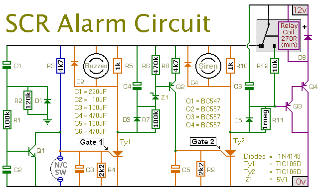
This is a simple SCR-based burglar alarm circuit. Its features include automatic exit and entry delays, along with a timed bell cut-off and reset. It is designed to be used with the usual types of normally-closed input devices such...

When power is applied to the circuit, SCR1 is off, resulting in no bias current path to ground; thus, LM317 operates as a current regulator. The LM317 is connected to the battery through steering diode D1, limiting resistor R1,...

Unijunction transistors Q1 and Q2 are configured as relaxation-type sawtooth oscillators. Transistor Q1 serves as the low-frequency control oscillator, while Q2 functions as the tone generator. Sawtooth waveforms are generated at the emitter terminals. In the absence of resistor...

This circuit of an FM radio-controlled anti-theft alarm can be utilized with any vehicle that has a 6 to 12-volt DC supply system. The mini VHF FM transmitter is installed in the vehicle during the night when it is...

The 7555 timer IC used is a low power version of the standard 555 timer. A super bright red LED is utilized because it provides a bright flash with low current. The 7555 timer IC is a versatile low-power component...