
12 Volt Car Lamp Dimmer Circuit Design using 555 Timer
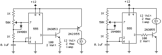
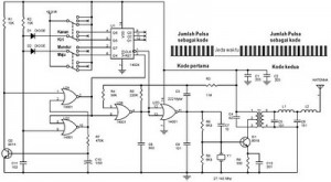
The 12 Volt Car Lamp Dimmer Circuit utilizes a 555 Timer in astable mode to control the brightness of a 25-watt car lamp. The circuit consists of a 555 Timer IC, resistors, capacitors, and a transistor to handle the load.
In this configuration, the 555 Timer generates a PWM (Pulse Width Modulation) signal, which is used to control the average power delivered to the lamp. The duty cycle of the PWM signal can be adjusted by varying the resistance values of the connected resistors, allowing for precise control over the brightness of the lamp.
Typically, a potentiometer is included in the circuit to enable the user to adjust the resistance, thereby altering the duty cycle and achieving the desired dimming effect. The output from the 555 Timer drives a transistor, which acts as a switch to control the lamp. The transistor must be chosen based on the current requirements of the lamp to ensure it can handle the load without overheating.
Capacitors are used in the timing circuit to stabilize the operation of the 555 Timer and filter any noise that may affect performance. The circuit operates at 12 volts, making it suitable for automotive applications.
Overall, this dimmer circuit is a practical solution for controlling the brightness of car lamps, enhancing both functionality and aesthetics while providing an efficient use of power.The following schematic diagram shows the 12 Volt Car Lamp Dimmer Circuit Design using 555 Timer. This circuit design can be used to dim a standard 25 watt.. 🔗 External reference
Related Circuits
This circuit generates audio musical notes that can be heard from a distance of up to 10 meters. It consists of two main components: an infrared (IR) music transmitter and an IR music receiver. The IR music transmitter operates...
This project involves a simple touch switch circuit that can also be utilized to activate a relay instead of an LED and resistor. The circuit exhibits high sensitivity due to the use of two transistors configured as a Darlington...
The PWM circuit is causing the inverter's current consumption to reach a dangerous level of 14 Amps. A potential solution involves reducing the drive voltage to the gates of the MOSFETs by controlling the base voltage of the buffer...
The following circuit illustrates a schematic diagram for a remote control toy car. Features: it does not affect the performance of the original design. The remote control toy car schematic circuit diagram typically consists of several key components that work...
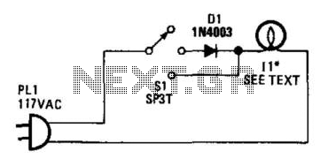
Lamp II is a household lamp. When the switch is in the center position, the lamp operates on half-wave rectified AC; the effective voltage that the lamp receives is reduced, which dims it. Lamp II can accommodate a power...
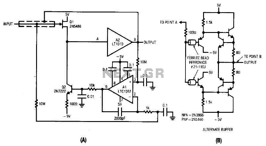
The difference between the amplified signals is utilized to establish the bias for Q1 and Q2 current channels. Q1 regulates the gate-source voltage (VGS) to the necessary level corresponding to the circuit's input and potential output. A 2000 pF...
Warning: include(partials/cookie-banner.php): Failed to open stream: Permission denied in /var/www/html/nextgr/view-circuit.php on line 713
Warning: include(): Failed opening 'partials/cookie-banner.php' for inclusion (include_path='.:/usr/share/php') in /var/www/html/nextgr/view-circuit.php on line 713